MZ3500
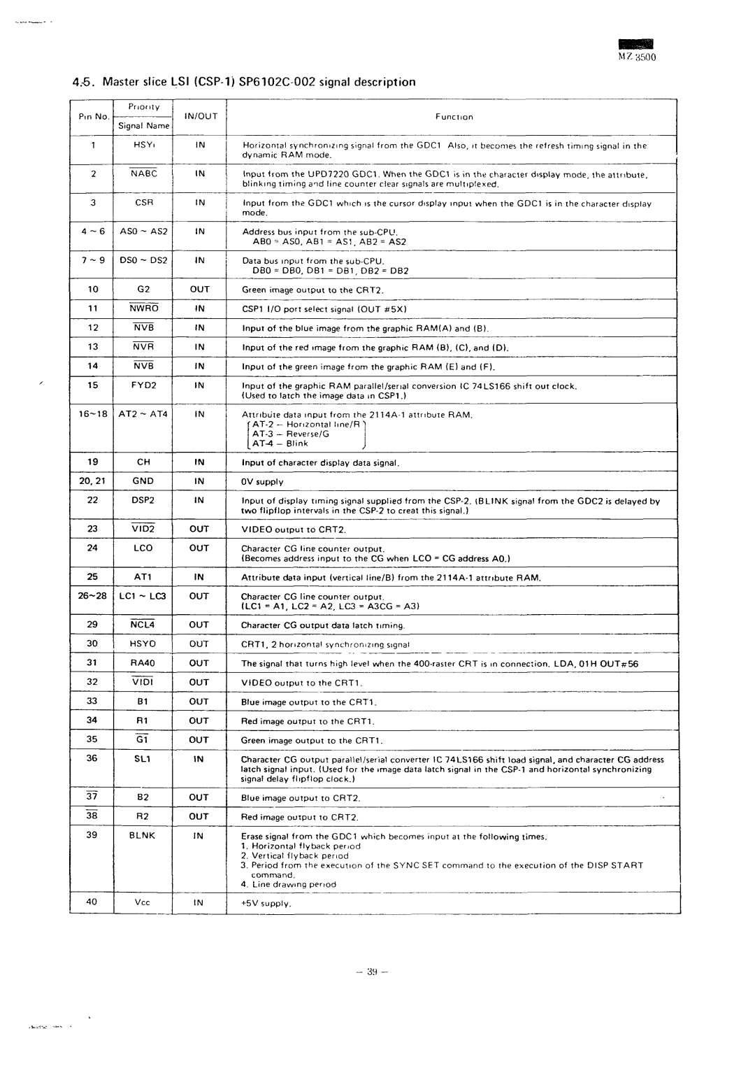
4/6. Master slice LSI (CSP-1) SP6102C 002 signal description
Priority
Signal Name
1 HSYi IN
2 NABC IN
3 CSR IN
4 - 6 ASO - AS2 IN
7 - 9 DSO - DS2 IN
10 G2 OUT
11 NWRO IN
12 NVB IN
13 NVR IN
14 NVB IN
15 FYD2 IN
19 CH IN
20.21 GND IN
22 DSP2 IN
23 VID2 OUT
24 LCD OUT
25 AT1 IN
29 NCL4 OUT
30 HSYO OUT
31 RA40 OUT
32 VIDI OUT
33 B1 OUT
34 R1 OUT
35 Of OUT
36 SL1 IN
37 B2 OUT
38 R2 OUT
39 BLNK IN
40 Vcc IN
Horizontal synchronizing signal from the GDC1 Also, it becomes the refresh timing signal in the dynamic RAM mode.
Input from the UPD7220 GDC1. When the GDC1 is in the character display mode, the attribute, blinking timing and line counter ciear signals are multiplexed.
Input from the GDC1 which is the cursor display input when the GDC1 is in the character display mode.
Address bus input from the
ABO = ASO, AB1 = AS1 , AB2 = AS2
Data bus input from the
DBO = DBO, DB1 = DB1 , DB2 = DB2
Green image output to the CRT2.
CSP1 I/O port select signal (OUT #5X)
Input of the blue image from the graphic RAM(A) and (B).
Input of the red image from the graphic RAM (B), (C), and (D).
Input of the green image from the graphic RAM (E) and (F).
Input of the graphic RAM parallel/serial conversion 1C 74LS166 shift out clock. (Used to latch the image data in CSP1 .)
Attribute data input from the
f | - | Horizontal Ime/R "] | |
- | Reverse/G |
| |
- | Blink | J | |
Input of character display data signal.
0V supply
Input of display timing signal supplied from the
VIDEO output to CRT2.
Character CG line counter output.
(Becomes address input to the CG when LCD = CG address AO.)
Attribute data input (vertical line/B) from the
Character CG line counter output.
(LC1 = A1, LC2 = A2, LC3 = A3CG = A3)
Character CG output data latch timing.
CRT1 , 2 horizontal synchronizing signal
The signal that turns high level when the
VIDEO output to the CRT1 .
Blue image output to the CRT1.
Red image output to the CRT1.
Green image output to the CRT1.
Character CG output parallel/serial converter 1C 74LS166 shift load signal, and character CG address latch signal input. (Used for the image data latch signal in the
Blue image output to CRT2.
Red image output to CRT2.
Erase signal from the GDC1 which becomes input at the following times.
1.Horizontal flyback period
2.Vertical flyback period
3.Period from the execution of the SYNC SET command to the execution of the DISP START command.
4.Line drawing period
+5V supply.
- 39 -