CHAPTER 7 Wireless Configuration
Wireless Distribution System (WDS)
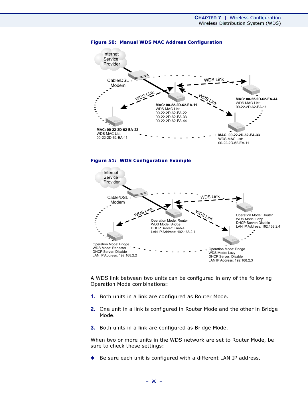
Figure 50: Manual WDS MAC Address Configuration
Internet
Service
Provider
Cable/DSL
Modem
WDS Link
Link
WDS
MAC:
WDS MAC List:
WDS | Link |
|
MAC:
WDS MAC List:
MAC: |
|
WDS MAC List: |
|
MAC: | |
WDS MAC List: | |
| |
| |
|
|
Figure 51: WDS Configuration Example
Internet |
|
|
|
| ||
Service |
|
|
|
| ||
Provider |
|
|
|
| ||
|
|
|
| WDS | Link | |
| Cable/DSL |
|
| |||
|
|
|
| |||
| Modem |
|
|
|
|
|
|
|
| Link | WDS |
|
|
|
| WDS |
| Link | ||
|
|
| Operation Mode: Router |
| ||
|
|
|
|
|
| |
WDS Mode: Bridge
DHCP Server: Enable
LAN IP Address: 192.168.2.1
Operation Mode: Router
WDS Mode: Lazy
DHCP Server: Disable
LAN IP Address: 192.168.2.4
Operation Mode: Bridge |
|
|
|
WDS Mode: Repeater |
| Operation Mode: Bridge |
|
DHCP Server: Disable |
|
| |
| WDS Mode: Lazy |
| |
LAN IP Address: 192.168.2.2 |
| ||
DHCP Server: Disable |
| ||
|
|
| |
|
| LAN IP Address: 192.168.2.3 | |
A WDS link between two units can be configured in any of the following Operation Mode combinations:
1.Both units in a link are configured as Router Mode.
2.One unit in a link is configured in Router Mode and the other in Bridge Mode.
3.Both units in a link are configured as Bridge Mode.
When two or more units in the WDS network are set to Router Mode, be sure to check these settings:
◆Be sure each unit is configured with a different LAN IP address.
– 90 –