and Device Port. In other words, this request is passed through the
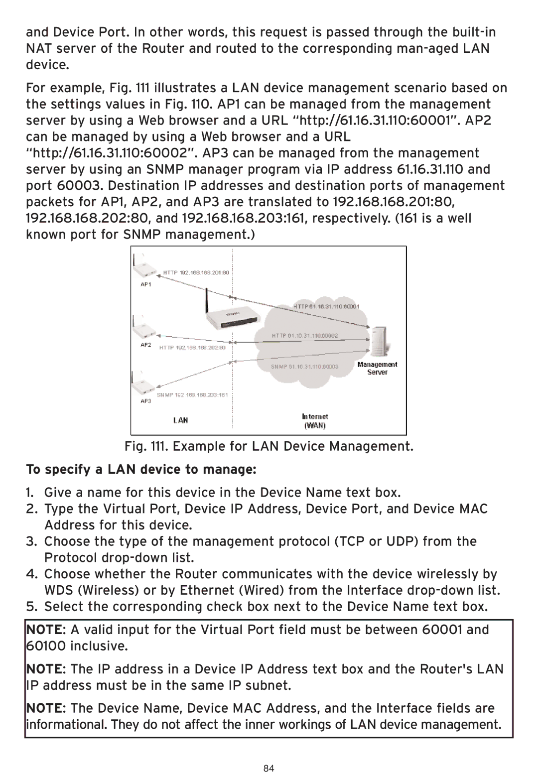
For example, Fig. 111 illustrates a LAN device management scenario based on the settings values in Fig. 110. AP1 can be managed from the management server by using a Web browser and a URL “http://61.16.31.110:60001”. AP2 can be managed by using a Web browser and a URL “http://61.16.31.110:60002”. AP3 can be managed from the management server by using an SNMP manager program via IP address 61.16.31.110 and port 60003. Destination IP addresses and destination ports of management packets for AP1, AP2, and AP3 are translated to 192.168.168.201:80, 192.168.168.202:80, and 192.168.168.203:161, respectively. (161 is a well known port for SNMP management.)
Fig. 111. Example for LAN Device Management.
To specify a LAN device to manage:
1.Give a name for this device in the Device Name text box.
2.Type the Virtual Port, Device IP Address, Device Port, and Device MAC Address for this device.
3.Choose the type of the management protocol (TCP or UDP) from the Protocol
4.Choose whether the Router communicates with the device wirelessly by WDS (Wireless) or by Ethernet (Wired) from the Interface
5.Select the corresponding check box next to the Device Name text box.
NOTE: A valid input for the Virtual Port field must be between 60001 and 60100 inclusive.
NOTE: The IP address in a Device IP Address text box and the Router's LAN IP address must be in the same IP subnet.
NOTE: The Device Name, Device MAC Address, and the Interface fields are informational. They do not affect the inner workings of LAN device management.
84