Rear
1
|
| (HD15) | 2(BNC) |
|
R |
| B |
| |
G | HD | VD |
OPTION OSD
OPT I ON |
|
|
|
L ANGUAGE | JPN | ENG | FRA |
| DEU | ESP | I TA |
OSD POS I T I ON : R I GHT | BOTTOM | ||
OSD MENU | NORMAL | EXPERT | |
LOCK | UNLOCK | LOCK | |
I NPUT : BNC | 84.4kHz / 72Hz | ||
SELECT |
| SET |
|
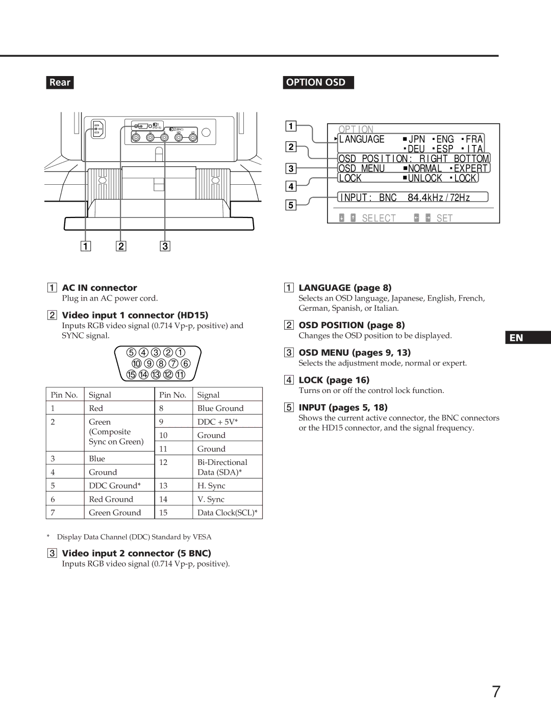
1AC IN connector
Plug in an AC power cord.
2Video input 1 connector (HD15)
Inputs RGB video signal (0.714
| 5 |
| 4 | 3 | 2 | 1 |
| |
| 10 | 9 | 8 | 7 | 6 |
| ||
| 15 | 14 | 13 12 | 11 |
| |||
|
|
|
|
|
|
| ||
Pin No. | Signal |
|
|
| Pin No. | Signal | ||
1 | Red |
|
|
| 8 |
|
| Blue Ground |
2 | Green |
|
|
| 9 |
|
| DDC + 5V* |
| (Composite |
|
|
| 10 |
| Ground | |
| Sync on Green) |
|
| |||||
|
| 11 |
| Ground | ||||
|
|
|
|
|
| |||
3 | Blue |
|
|
| ||||
|
|
| 12 |
| ||||
4 | Ground |
|
|
|
| |||
|
|
|
|
|
| Data (SDA)* | ||
5 | DDC Ground* |
|
| 13 |
| H. Sync | ||
6 | Red Ground |
|
|
| 14 |
| V. Sync | |
7 | Green Ground |
| 15 |
| Data Clock(SCL)* | |||
*Display Data Channel (DDC) Standard by VESA
3Video input 2 connector (5 BNC)
Inputs RGB video signal (0.714
1LANGUAGE (page 8)
Selects an OSD language, Japanese, English, French, German, Spanish, or Italian.
2OSD POSITION (page 8)
Changes the OSD position to be displayed.
3OSD MENU (pages 9, 13)
Selects the adjustment mode, normal or expert.
4LOCK (page 16)
Turns on or off the control lock function.
5INPUT (pages 5, 18)
Shows the current active connector, the BNC connectors or the HD15 connector, and the signal frequency.
EN
F
D
ES
I
J
7