Chapter 3 Preparations
3-4-3 Contents of the Expansion Menu
The contents of the Expansion menu are described in the table that follows.
•The item enclosed in a square in the “Settings” column indicates defaults.
•The letters “B” and “I” in the item number column indicate when a change to
|
| that setting becomes effective, just as in the Basic menu. |
| |||
|
| For details on the meaning of each letter, refer to Section | ||||
|
|
|
|
|
| |
|
| Expansion menu items |
|
|
| |
Item number | Display indication | Settings | Description |
|
|
|
101 | SELECTION FOR SEARCH | This item sets the method for putting the |
| |||
BI | DIAL ENABLE | dial direct | : The unit enters search mode when the search dial is turned from any | |||
|
|
| mode except while recording/editing are in progress. |
| ||
|
| via search key : The unit enters search mode when any of the following buttons is | ||||
|
|
| pressed: JOG, SHUTTLE, VAR. |
|
|
|
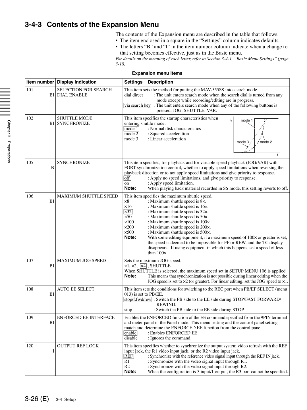
102 | SHUTTLE MODE | This item specifies the startup characteristics when | v | mode 1 |
| |
BI | SYNCHRONIZE | entering shuttle mode. |
| |||
|
|
| ||||
|
| mode 1 | : Normal disk characteristics |
|
|
|
|
| mode 2 | : Squared acceleration |
|
|
|
|
| mode 3 | : Linear acceleration |
| mode 3 | mode 2 |
|
|
|
|
| ||
|
|
|
|
|
| t |
105 | SYNCHRONIZE | This item specifies, for playback and for variable speed playback (JOG/VAR) with | ||||||
| B | FORT synchronization control, whether to apply speed limitations when reversing the | ||||||
|
| playback direction or to not apply speed limitations and give priority to response. | ||||||
|
| off |
|
|
|
| : Apply no speed limitations, and give priority to response. | |
|
| on |
|
|
|
| : Apply speed limitation. | |
|
| Note: | When playing back material recorded in SS mode, this setting reverts to off. | |||||
|
|
|
|
|
|
|
| |
106 | MAXIMUM SHUTTLE SPEED | This item specifies the maximum shuttle speed. | ||||||
| BI | ×8 |
|
|
|
| : Maximum shuttle speed is 8×. | |
|
| ×16 |
|
|
| : Maximum shuttle speed is 16×. | ||
|
| ×32 |
|
|
| : Maximum shuttle speed is 32×. | ||
|
| ×50 |
|
|
| : Maximum shuttle speed is 50×. | ||
|
| ×100 |
|
| : Maximum shuttle speed is 100×. | |||
|
| ×200 |
|
| : Maximum shuttle speed is 200×. | |||
|
| ×500 |
|
| : Maximum shuttle speed is 500×. | |||
|
| Note: | With some editing equipment, if a maximum speed of 100× or greater is set, | |||||
|
|
|
|
|
|
| the speed is deemed to be impossible for FF or REW, and the TC display | |
|
|
|
|
|
|
| disappears. If using equipment in which this happens, set a speed of less | |
|
|
|
|
|
|
| than 100×. | |
|
|
|
|
|
|
|
| |
107 | MAXIMUM JOG SPEED | Sets the maximum JOG speed. | ||||||
| BI | ×1, ×2, | ×4 , SHUTTLE | |||||
|
| When SHUTTLE is selected, the maximum speed set in SETUP MENU 106 is applied. | ||||||
|
| Note: | This means that synchronization is not possible during linear editing when the | |||||
|
|
|
|
|
|
| JOG speed is set to ×2 (or greater). For linear editing, set the JOG speed to ×1. | |
|
|
|
|
|
|
|
| |
108 | AUTO EE SELECT | This item sets the conditions for switching to the REC port when PB/EF SELECT (menu | ||||||
| BI | 013) is set to PB/EE. | ||||||
|
| stop/f.fwd/rew | : Switch the PB side to the EE side during STOP/FAST FORWARD/ | |||||
|
|
|
|
|
|
|
| REWIND. |
|
| stop |
| : Switch the PB side to the EE side during STOP. | ||||
|
|
|
|
|
|
|
| |
109 | ENFORCED EE INTERFACE | Enables the ENFORCED function of the EE command specified from the 9PIN terminal | ||||||
| BI | and meter panel in the Panel mode. This menu setting and the control panel setting | ||||||
|
| match and determine the ENFORCED EE function from the control panel. | ||||||
|
| enable |
| : Enables ENFORCED EE | ||||
|
| disable |
| : Ignores the command. | ||||
|
|
|
|
|
|
|
| |
120 | OUTPUT REF LOCK | This item specifies whether to synchronize the output system video refresh with the REF | ||||||
| I | input jack, the R1 video input jack, or the R2 video input jack. | ||||||
|
| REF |
| : Synchronize with the reference video signal input through the REF IN jack. | ||||
|
| R1 |
| : Synchronize with the video signal input through R1. | ||||
|
| R2 | : Synchronize with the video signal input through R2. | |||||
|
| Note: | When the configuration is 3 input/1 output, the R3 port cannot be specified. | |||||