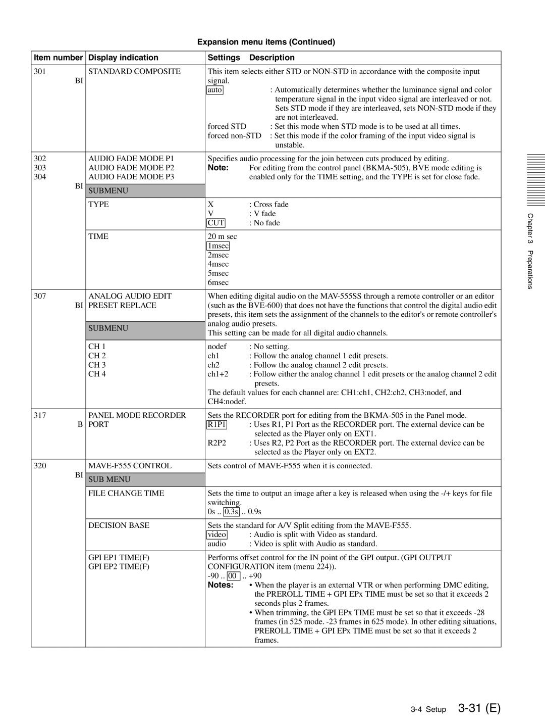
Expansion menu items (Continued)
Item number | Display indication | Settings | Description | ||||
|
|
|
|
|
|
| |
301 | STANDARD COMPOSITE | This item selects either STD or | |||||
BI |
| signal. |
| ||||
|
| auto |
|
|
|
| : Automatically determines whether the luminance signal and color |
|
|
|
|
|
|
| temperature signal in the input video signal are interleaved or not. |
|
|
|
|
|
|
| Sets STD mode if they are interleaved, sets |
|
|
|
|
|
|
| are not interleaved. |
|
| forced STD | : Set this mode when STD mode is to be used at all times. | ||||
|
| forced | |||||
|
|
|
|
|
|
| unstable. |
|
|
|
|
|
|
| |
302 | AUDIO FADE MODE P1 | Specifies audio processing for the join between cuts produced by editing. | |||||
303 | AUDIO FADE MODE P2 | Note: | For editing from the control panel | ||||
304 | AUDIO FADE MODE P3 |
|
|
|
|
| enabled only for the TIME setting, and the TYPE is set for close fade. |
BI |
|
|
|
|
|
|
|
SUBMENU |
|
|
|
|
|
| |
| TYPE | X | : Cross fade | ||||
|
| V | : V fade | ||||
|
| CUT |
|
|
| : No fade | |
|
|
|
|
|
|
|
|
| TIME | 20 m sec |
| ||||
|
| 1msec |
|
|
| ||
|
| 2msec |
|
|
| ||
|
| 4msec |
| ||||
|
| 5msec |
| ||||
|
| 6msec |
| ||||
|
|
|
|
|
|
| |
307 | ANALOG AUDIO EDIT | When editing digital audio on the | |||||
BI | PRESET REPLACE | (such as the | |||||
|
| presets, this item sets the assignment of the channels to the editor's or remote controller's | |||||
|
| analog audio presets. | |||||
| SUBMENU | ||||||
| This setting can be made for all digital audio channels. | ||||||
|
| ||||||
| CH 1 | nodef | : No setting. | ||||
| CH 2 | ch1 | : Follow the analog channel 1 edit presets. | ||||
| CH 3 | ch2 | : Follow the analog channel 2 edit presets. | ||||
| CH 4 | ch1+2 | : Follow either the analog channel 1 edit presets or the analog channel 2 edit | ||||
|
|
|
|
|
|
| presets. |
|
| The default values for each channel are: CH1:ch1, CH2:ch2, CH3:nodef, and | |||||
|
| CH4:nodef. |
| ||||
|
|
|
|
|
|
| |
317 | PANEL MODE RECORDER | Sets the RECORDER port for editing from the | |||||
B | PORT | R1P1 |
|
| : Uses R1, P1 Port as the RECORDER port. The external device can be | ||
|
|
|
|
|
|
| selected as the Player only on EXT1. |
|
| R2P2 | : Uses R2, P2 Port as the RECORDER port. The external device can be | ||||
|
|
|
|
|
|
| selected as the Player only on EXT2. |
|
|
|
|
|
|
| |
320 |
| Sets control of | |||||
BI |
|
|
|
|
|
|
|
SUB MENU |
|
|
|
|
|
| |
| FILE CHANGE TIME | Sets the time to output an image after a key is released when using the | |||||
|
| switching. |
| ||||
|
| 0s .. | 0.3s | .. 0.9s | |||
|
|
|
|
|
|
|
|
| DECISION BASE | Sets the standard for A/V Split editing from the | |||||
|
| video |
|
| : Audio is split with Video as standard. | ||
|
| audio |
|
| : Video is split with Audio as standard. | ||
|
|
|
|
|
|
| |
| GPI EP1 TIME(F) | Performs offset control for the IN point of the GPI output. (GPI OUTPUT | |||||
| GPI EP2 TIME(F) | CONFIGURATION item (menu 224)). | |||||
|
| 00 | .. +90 | ||||
|
| Notes: |
| • When the player is an external VTR or when performing DMC editing, | |||
|
|
|
|
|
|
| the PREROLL TIME + GPI EPx TIME must be set so that it exceeds 2 |
|
|
|
|
|
|
| seconds plus 2 frames. |
|
|
|
|
|
|
| • When trimming, the GPI EPx TIME must be set so that it exceeds |
|
|
|
|
|
|
| frames (in 525 mode. |
|
|
|
|
|
|
| PREROLL TIME + GPI EPx TIME must be set so that it exceeds 2 |
|
|
|
|
|
|
| frames. |
|
|
|
|
|
|
|
|
Chapter 3 Preparations
