P R E P A R A T I O N | For Machines Mfg. Since 3/11 |
In addition to the reservoirs, we also recommend that you lubricate all other points on the machine at this time. This can be accomplished by following the maintenance schedule on Page 65.
Note: If this lathe was shipped with oil in the reservoirs, do not change that oil until after the test run and
Adding Coolant
Add the coolant of your choice now. For detailed instructions on where the coolant tank is located and how to add fluid, refer to Coolant System Service subsection on Page 72.
Power Connection
After you have completed all previous setup instructions and circuit requirements, the machine is ready to be connected to the power supply.
Model SB1053
Connect a power cord that meets the Circuit Requirements on Page 18, as instructed later in this subsection. Attach a locking NEMA L15- 30 plug as directed by the plug manufacture, and insert it into a matching receptacle
that is connected to a circuit that meets the requirements listed on Page 18.
Model SB1054F & SB1055F
Due to the complexity required for planning, bending, and installing the conduit necessary for a
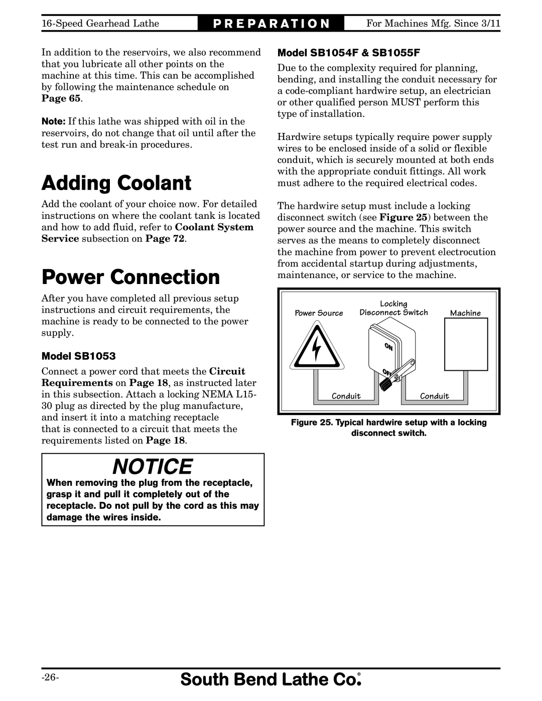
Hardwire setups typically require power supply wires to be enclosed inside of a solid or flexible conduit, which is securely mounted at both ends with the appropriate conduit fittings. All work must adhere to the required electrical codes.
The hardwire setup must include a locking disconnect switch (see Figure 25) between the power source and the machine. This switch serves as the means to completely disconnect the machine from power to prevent electrocution from accidental startup during adjustments, maintenance, or service to the machine.
|
| Locking |
|
Power Source | Disconnect Switch | Machine | |
Conduit | Conduit |
| |
Figure 25. Typical hardwire setup with a locking
disconnect switch.
When removing the plug from the receptacle, grasp it and pull it completely out of the receptacle. Do not pull by the cord as this may damage the wires inside.