For Machines Mfg. Since 3/11 | O P E R A T I O N |
Manual Feed
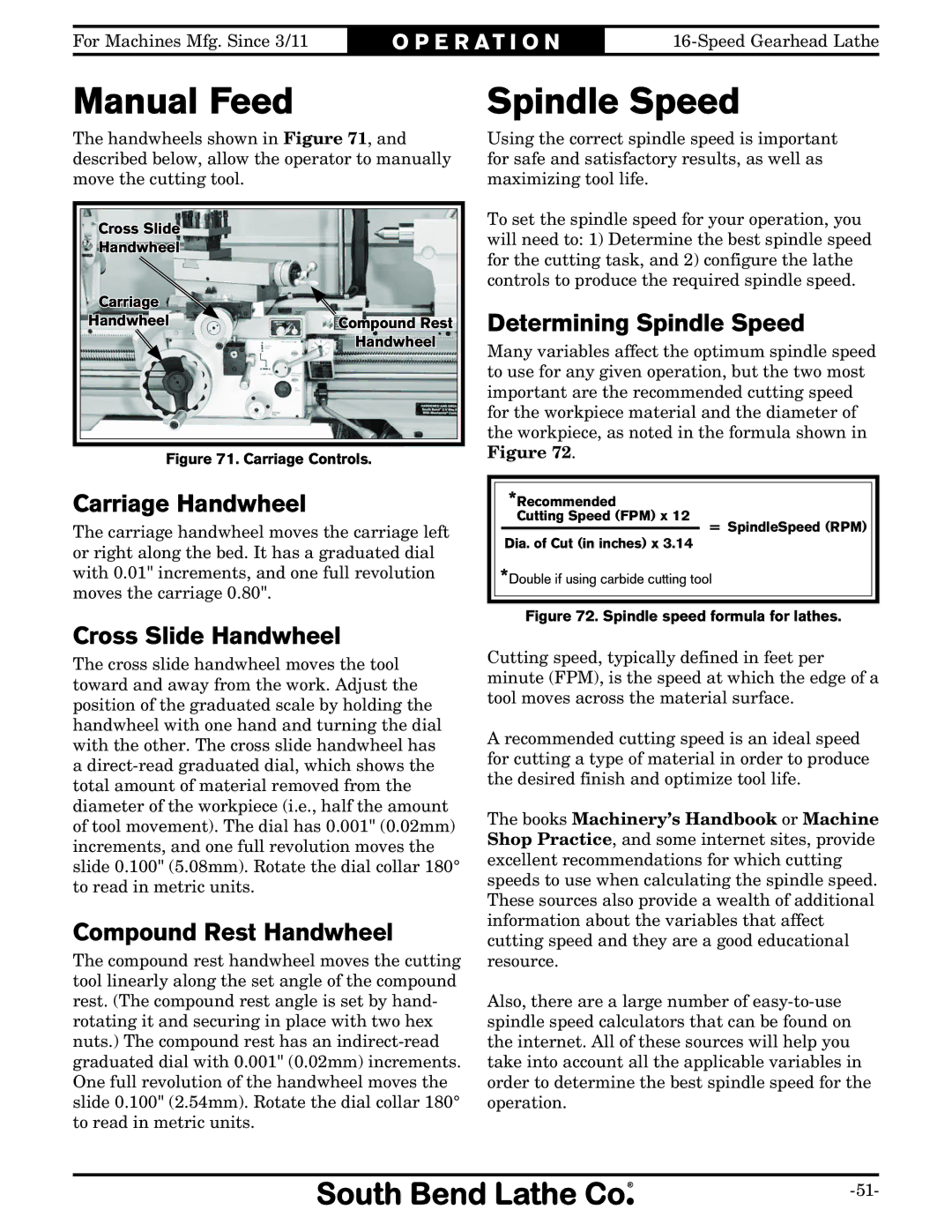
The handwheels shown in Figure 71, and described below, allow the operator to manually move the cutting tool.
Cross Slide
H![]()
![]() andwheel
andwheel
Carriage |
|
Handwheel | Compound Rest |
| Handwheel |
Figure 71. Carriage Controls.
Carriage Handwheel
The carriage handwheel moves the carriage left or right along the bed. It has a graduated dial with 0.01" increments, and one full revolution moves the carriage 0.80".
Cross Slide Handwheel
The cross slide handwheel moves the tool toward and away from the work. Adjust the position of the graduated scale by holding the handwheel with one hand and turning the dial with the other. The cross slide handwheel has a
Compound Rest Handwheel
The compound rest handwheel moves the cutting tool linearly along the set angle of the compound rest. (The compound rest angle is set by hand- rotating it and securing in place with two hex nuts.) The compound rest has an
Spindle Speed
Using the correct spindle speed is important for safe and satisfactory results, as well as maximizing tool life.
To set the spindle speed for your operation, you will need to: 1) Determine the best spindle speed for the cutting task, and 2) configure the lathe controls to produce the required spindle speed.
Determining Spindle Speed
Many variables affect the optimum spindle speed to use for any given operation, but the two most important are the recommended cutting speed for the workpiece material and the diameter of the workpiece, as noted in the formula shown in Figure 72.
*Recommended
Cutting Speed (FPM) x 12
= SpindleSpeed (RPM)
Dia. of Cut (in inches) x 3.14
*Double if using carbide cutting tool
Figure 72. Spindle speed formula for lathes.
Cutting speed, typically defined in feet per minute (FPM), is the speed at which the edge of a tool moves across the material surface.
A recommended cutting speed is an ideal speed for cutting a type of material in order to produce the desired finish and optimize tool life.
The books Machinery’s Handbook or Machine Shop Practice, and some internet sites, provide excellent recommendations for which cutting speeds to use when calculating the spindle speed. These sources also provide a wealth of additional information about the variables that affect cutting speed and they are a good educational resource.
Also, there are a large number of