P A R T S | For Machines Mfg. Since 3/11 |
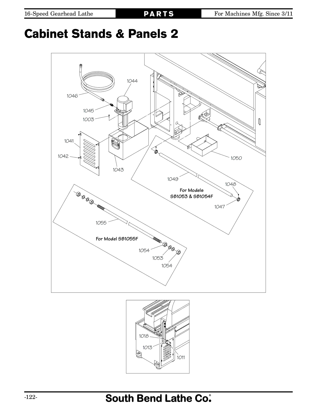
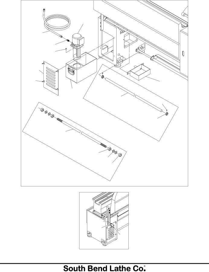
Cabinet Stands & Panels 2
1044
1046
1045
1003
1041 |
|
1042 | 1050 |
|
1043
1049
1048
For Models
SB1053 & SB1054F
1047
1055
For Model SB1055F
1054
1053
1054
1018 ![]()
![]()
![]()
![]()
1013 ![]()
1011
P A R T S | For Machines Mfg. Since 3/11 |
1044
1046
1045
1003
1041 |
|
1042 | 1050 |
|
1043
1049
1048
For Models
SB1053 & SB1054F
1047
1055
For Model SB1055F
1054
1053
1054
1018 ![]()
![]()
![]()
![]()
1013 ![]()
1011