O P E R A T I O N | For Machines Mfg. Since 3/11 |
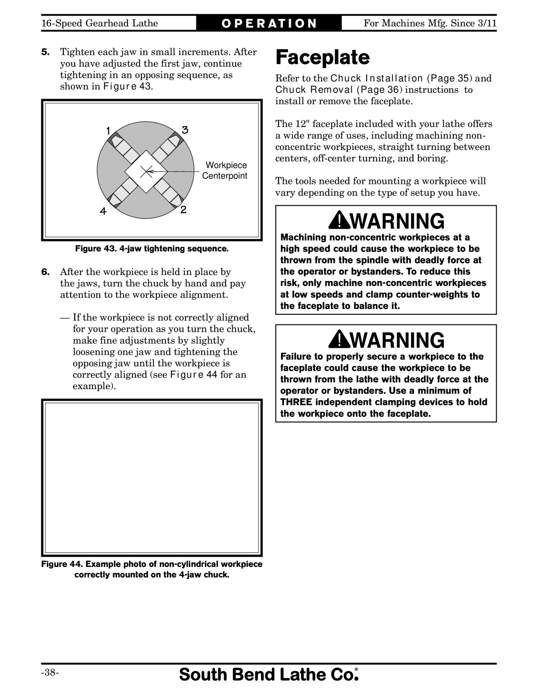
5.Tighten each jaw in small increments. After you have adjusted the first jaw, continue tightening in an opposing sequence, as shown in Figure 43.
13
Workpiece
Centerpoint
42
Figure 43. 4-jaw tightening sequence.
6.After the workpiece is held in place by the jaws, turn the chuck by hand and pay attention to the workpiece alignment.
—If the workpiece is not correctly aligned for your operation as you turn the chuck, make fine adjustments by slightly loosening one jaw and tightening the opposing jaw until the workpiece is correctly aligned (see Figure 44 for an example).
Faceplate
Refer to the Chuck Installation (Page 35) and Chuck Removal (Page 36) instructions to install or remove the faceplate.
The 12" faceplate included with your lathe offers a wide range of uses, including machining non- concentric workpieces, straight turning between centers,
The tools needed for mounting a workpiece will vary depending on the type of setup you have.
Machining
Failure to properly secure a workpiece to the faceplate could cause the workpiece to be thrown from the lathe with deadly force at the operator or bystanders. Use a minimum of THREE independent clamping devices to hold the workpiece onto the faceplate.