O P E R A T I O N | For Machines Mfg. Since 3/11 |
3.The configuration string of characters to the right of the selected feed rate (LCS8W) displays the positions to set the feed controls for a feed rate of 0.18mm/rev.
4.Position the controls as indicated in the following instructions. If needed, use the chuck key to rock the spindle
a)Move the feed range lever to the low (L) position.
b)Point the left gearbox lever to the "C".
c)Move the middle gearbox lever to the "S".
d)Position the bottom gearbox lever in the "8" slot.
e)Point the right gearbox lever to the "W".
The lathe is now set up for a power feed rate of 0.18mm per spindle revolution.
End Gears
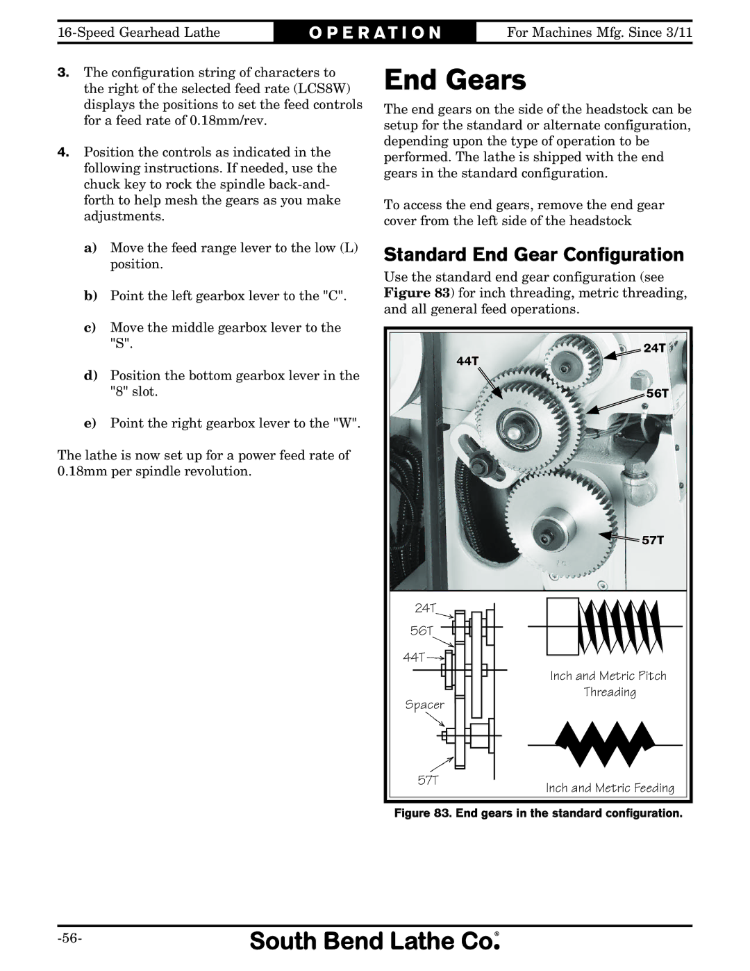
The end gears on the side of the headstock can be setup for the standard or alternate configuration, depending upon the type of operation to be performed. The lathe is shipped with the end gears in the standard configuration.
To access the end gears, remove the end gear cover from the left side of the headstock
Standard End Gear Configuration
Use the standard end gear configuration (see Figure 83) for inch threading, metric threading, and all general feed operations.
| 24T |
| 44T |
| 56T |
| 57T |
24T |
|
56T |
|
44T |
|
| Inch and Metric Pitch |
Spacer | Threading |
| |
57T | Inch and Metric Feeding |
|
