For Machines Mfg. Since 3/11 | I N T R O D U C T I O N |
Carriage Controls
C
A
B
E![]()
![]()
ND
MI F![]()
![]()
KH![]()
![]()
L![]()
![]() JG
JG
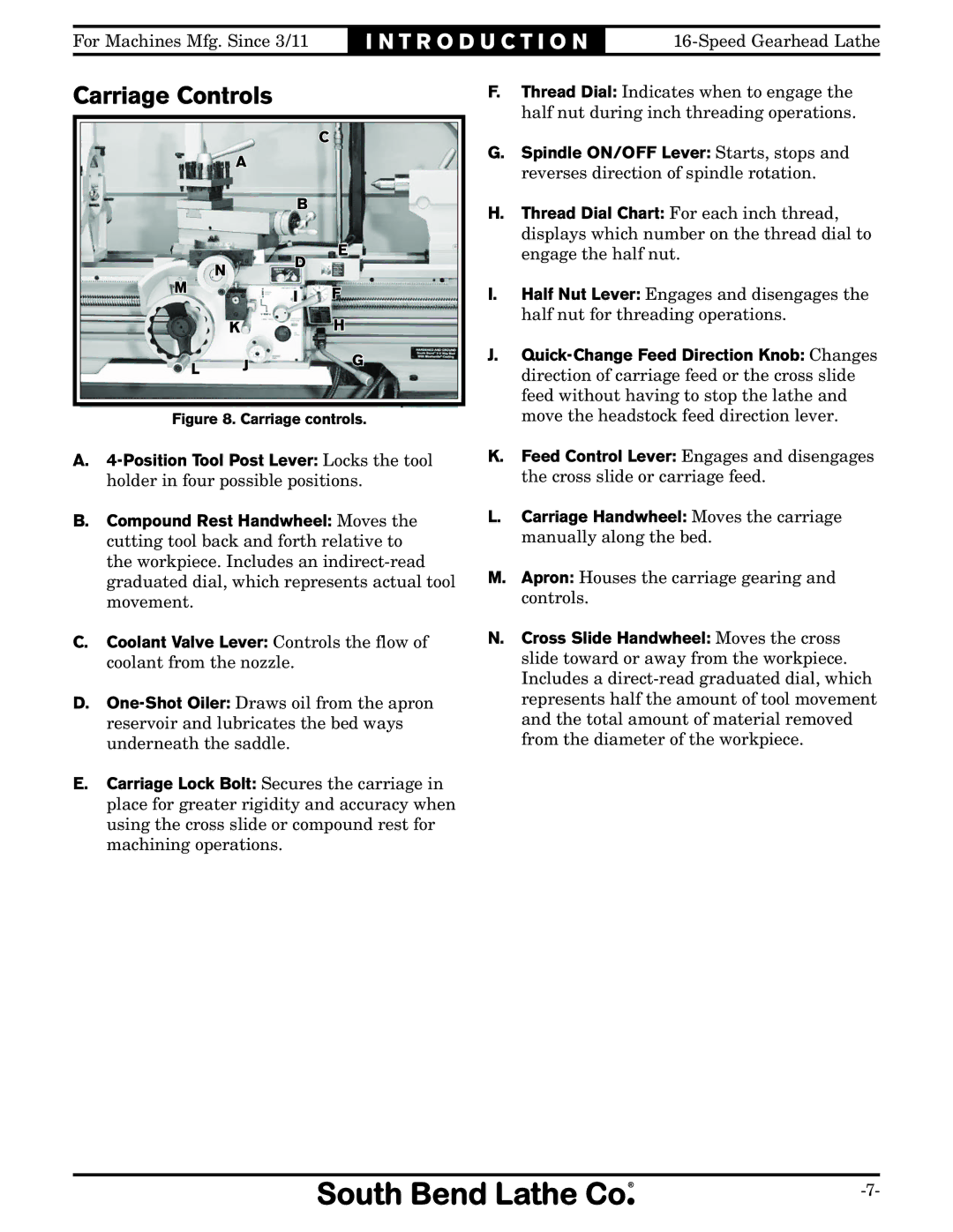
Figure 8. Carriage controls.
A.
B.Compound Rest Handwheel: Moves the cutting tool back and forth relative to the workpiece. Includes an
C.Coolant Valve Lever: Controls the flow of coolant from the nozzle.
D.
E.Carriage Lock Bolt: Secures the carriage in place for greater rigidity and accuracy when using the cross slide or compound rest for machining operations.
F.Thread Dial: Indicates when to engage the half nut during inch threading operations.
G.Spindle ON/OFF Lever: Starts, stops and reverses direction of spindle rotation.
H.Thread Dial Chart: For each inch thread, displays which number on the thread dial to engage the half nut.
I.Half Nut Lever: Engages and disengages the half nut for threading operations.
J.
K.Feed Control Lever: Engages and disengages the cross slide or carriage feed.
L.Carriage Handwheel: Moves the carriage manually along the bed.
M.Apron: Houses the carriage gearing and controls.
N.Cross Slide Handwheel: Moves the cross slide toward or away from the workpiece. Includes a