Connecting Vacuum Pumps and Filter Chambers to the Network
Connecting Vacuum Pumps
Make sure that all previous installation steps have been done first before starting this task. You’ll use two yellow patch cords to connect.
To connect a vacuum pump to the network:
1.Attach one connector of the first yellow patch cord to the lower terminal on the vacuum pump terminal box. Tighten the cord grip ring until snug.
2.Attach the other connector to the upper left terminal of the ArmorBlock. Tighten the cord grip ring until snug.
3.Attach one connector of a yellow patch cord to the upper terminal on the vacuum pump terminal box. Tighten the cord grip ring until snug.
4.Attach the other connector to the upper right terminal of the ArmorBlock. Tighten the cord grip ring until snug.
Note: Retain the terminal caps from the ArmorBlock. They may be used later.
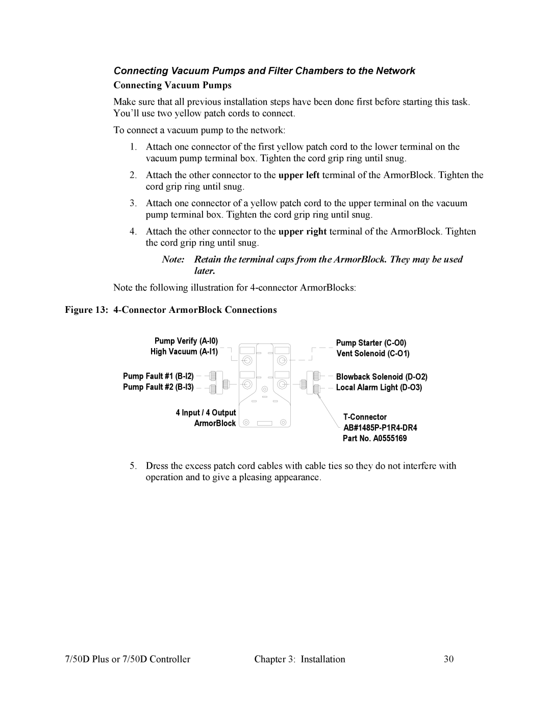
Note the following illustration for
Figure 13: 4-Connector ArmorBlock Connections
Pump Verify
High Vacuum
Pump Fault #1
Pump Fault #2
4 Input / 4 Output
ArmorBlock
Pump Starter
Blowback Solenoid
Part No. A0555169
5.Dress the excess patch cord cables with cable ties so they do not interfere with operation and to give a pleasing appearance.
7/50D Plus or 7/50D Controller | Chapter 3: Installation | 30 |