Chapter 3
Measurements
37
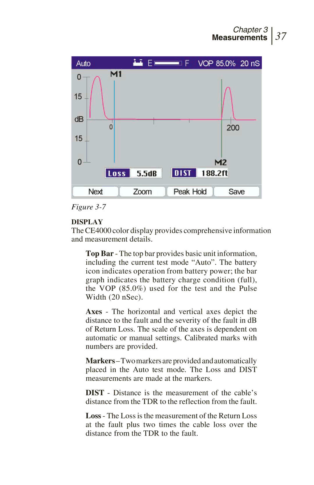
Figure
DISPLAY
The CE4000 color display provides comprehensive information and measurement details.
Top Bar - The top bar provides basic unit information, including the current test mode “Auto”. The battery icon indicates operation from battery power; the bar graph indicates the battery charge condition (full), the VOP (85.0%) used for the test and the Pulse Width (20 nSec).
Axes - The horizontal and vertical axes depict the distance to the fault and the severity of the fault in dB of Return Loss. The scale of the axes is dependent on automatic or manual settings. Calibrated marks with numbers are provided.
Markers – Two markers are provided and automatically placed in the Auto test mode. The Loss and DIST measurements are made at the markers.
DIST - Distance is the measurement of the cable’s distance from the TDR to the reflection from the fault.
Loss - The Loss is the measurement of the Return Loss at the fault plus two times the cable loss over the distance from the TDR to the fault.