Chapter 3
Measurements
29
Chapter 3 Measurements
TDR BASICS
Locating Cable Faults
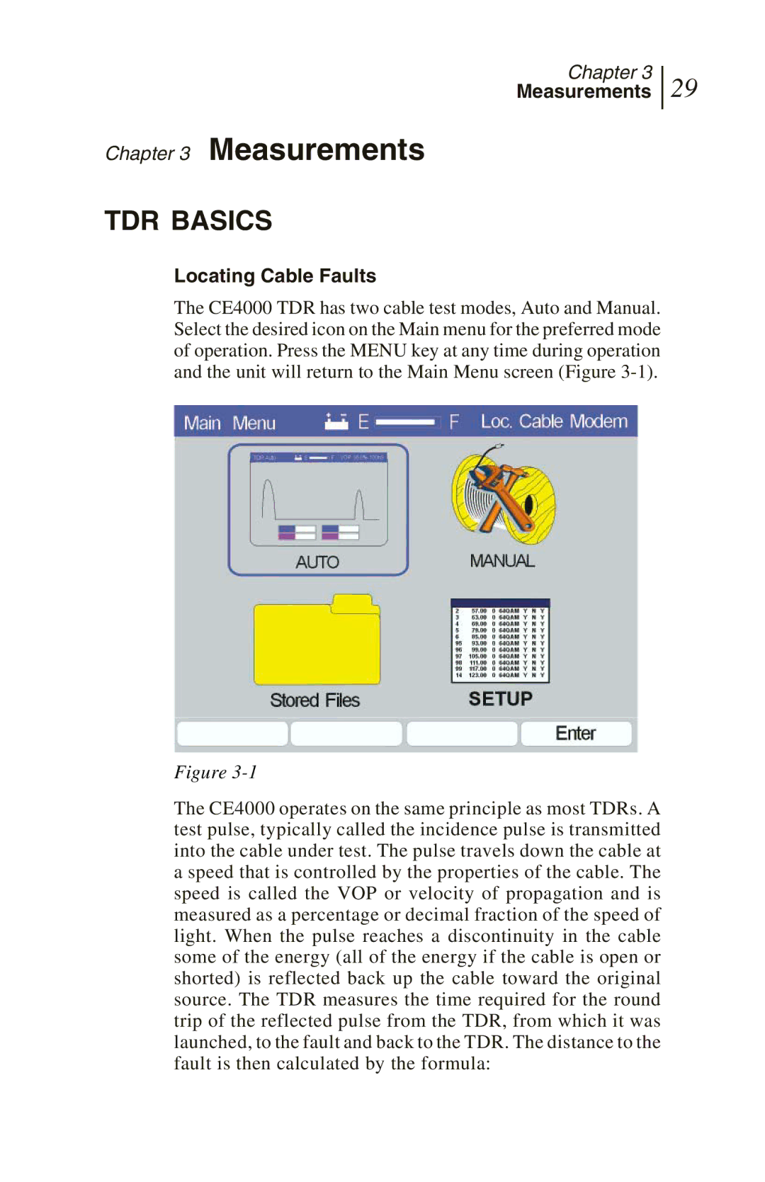
The CE4000 TDR has two cable test modes, Auto and Manual. Select the desired icon on the Main menu for the preferred mode of operation. Press the MENU key at any time during operation and the unit will return to the Main Menu screen (Figure
Figure
The CE4000 operates on the same principle as most TDRs. A test pulse, typically called the incidence pulse is transmitted into the cable under test. The pulse travels down the cable at a speed that is controlled by the properties of the cable. The speed is called the VOP or velocity of propagation and is measured as a percentage or decimal fraction of the speed of light. When the pulse reaches a discontinuity in the cable some of the energy (all of the energy if the cable is open or shorted) is reflected back up the cable toward the original source. The TDR measures the time required for the round trip of the reflected pulse from the TDR, from which it was launched, to the fault and back to the TDR. The distance to the fault is then calculated by the formula: