|
|
|
|
|
| Chapter 1: Introduction | |
|
|
|
|
|
|
|
|
|
|
|
|
|
|
|
|
|
|
|
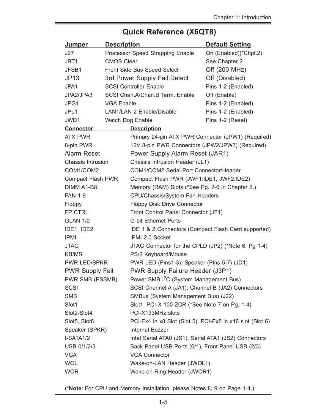
| Quick Reference (X6QT8) | |||
Jumper |
| Description | Default Setting | ||||
|
|
|
|
|
|
| |
J27 |
| Processor Speed Strapping Enable | On (Enabled)(*Chpt.2) | ||||
JBT1 | CMOS Clear | See Chapter 2 | |||||
JFSB1 | Front Side Bus Speed Select | Off (200 MHz) | |||||
JP13 | 3rd Power Supply Fail Detect | Off (Disabled) | |||||
JPA1 | SCSI Controller Enable | Pins | |||||
JPA2/JPA3 | SCSI Chan.A/Chan.B Term. Enable | Off (Enable) | |||||
JPG1 | VGA Enable | Pins | |||||
JPL1 | LAN1/LAN 2 Enable/Disable | Pins | |||||
JWD1 | Watch Dog Enable | Pins | |||||
Connector |
|
|
| Description |
|
| |
ATX PWR |
|
| Primary | ||||
|
| 12V | |||||
Alarm Reset |
|
| Power Supply Alarm Reset (JAR1) | ||||
Chassis Intrusion |
| Chassis Intrusion Header (JL1) | |||||
COM1/COM2 |
|
| COM1/COM2 Serial Port Connector/Header | ||||
Compact Flash PWR | Compact Flash PWR (JWF1:IDE1, JWF2:IDE2) | ||||||
DIMM |
|
| Memory (RAM) Slots (*See Pg. | ||||
FAN |
|
| CPU/Chassis/System Fan Headers | ||||
Floppy |
|
| Floppy Disk Drive Connector |
|
| ||
FP CTRL |
| Front Control Panel Connector (JF1) | |||||
GLAN 1/2 |
|
|
| ||||
IDE1, IDE2 |
|
| IDE 1 & 2 Connectors (Compact Flash Card supported) | ||||
IPMI |
|
| IPMI 2.0 Socket |
|
| ||
JTAG |
| JTAG Connector for the CPLD (JP2) (*Note 6, Pg | |||||
KB/MS |
| PS/2 Keyboard/Mouse |
|
| |||
PWR LED/SPKR |
| PWR LED | |||||
PWR Supply Fail |
| PWR Supply Failure Header (J3P1) | |||||
PWR SMB (PSSMB) |
| Power SMB I2C (System Management Bus) | |||||
SCSI |
|
| SCSI Channel A (JA1), Channel B (JA2) Connectors | ||||
SMB |
|
| SMBus (System Management Bus) (J22) | ||||
Slot1 |
| Slot1: | |||||
|
|
| |||||
Slot5, Slot6 |
|
| |||||
Speaker (SPKR) | Internal Buzzer |
|
| ||||
|
|
| Intel Serial ATA0 (JS1), Serial ATA1 (JS2) Connectors | ||||
USB 0/1/2/3 |
|
| Back Panel USB Ports (0/1), Front Panel USB (2/3) | ||||
VGA |
|
| VGA Connector |
|
| ||
WOL |
|
| |||||
WOR |
|
| |||||
(*Note: For CPU and Memory Installation, please Notes 8, 9 on Page