Chapter 2: Installation
CMOS Clear
JBT1 is used to clear CMOS. Instead of pins, this "jumper" consists of contact pads to prevent the accidental clearing of CMOS. To clear CMOS, use a metal object such as a small screwdriver to touch both pads at the same time to short the connection. Always remove the AC power cord from the system before clear- ing CMOS. Note: For an ATX power supply, you must completely shut down the system, remove the AC power cord and then short JBT1 to clear CMOS.
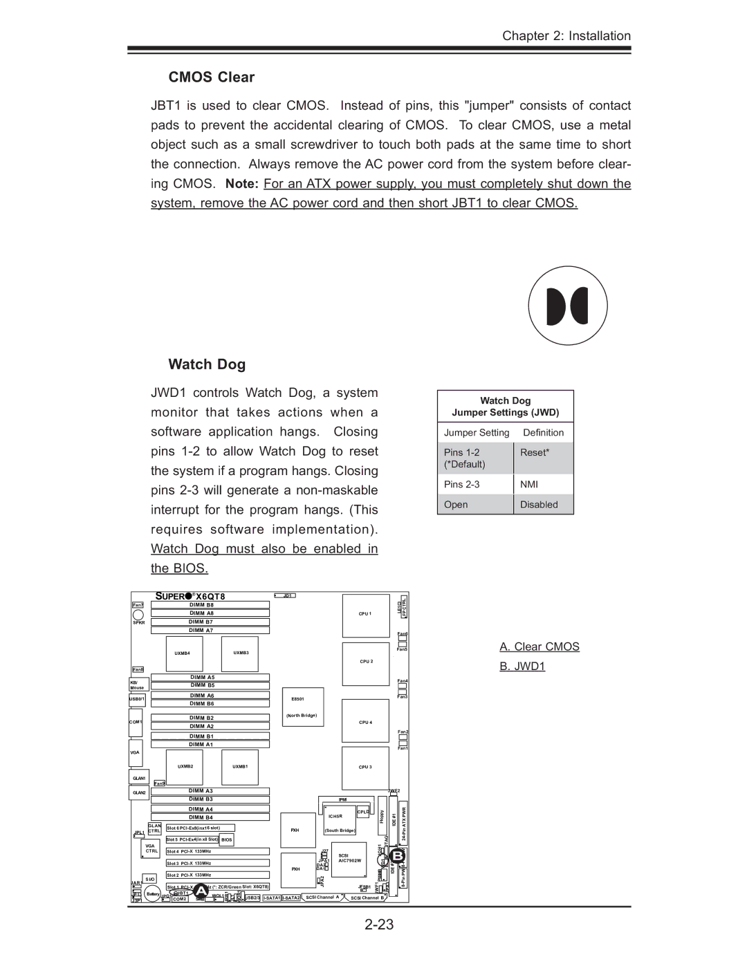
Watch Dog
JWD1 controls Watch Dog, a system monitor that takes actions when a software application hangs. Closing pins
Watch Dog
Jumper Settings (JWD)
Jumper Setting | Defi nition | |
Pins | Reset* | |
(*Default) |
| |
Pins | NMI | |
Open | Disabled | |
|
|
| SUPER | ® | X6QT8 |
|
| JD1 |
|
|
|
|
|
|
|
|
|
| |||||
Fan7 |
|
|
|
| DIMM B8 |
|
|
|
|
|
|
|
|
|
|
|
| LE1 | CTRL |
| |
|
|
|
|
|
|
|
|
|
|
|
|
|
|
|
|
|
| ||||
|
|
|
|
| DIMM A8 |
|
|
|
|
|
|
| CPU 1 |
|
|
|
| FP |
| ||
|
|
|
|
|
|
|
|
|
|
|
|
|
|
|
|
|
| ||||
SPKR |
|
|
|
| DIMM B7 |
|
|
|
|
|
|
|
|
|
|
|
|
|
|
| |
|
|
|
|
| DIMM A7 |
|
|
|
|
|
|
|
|
|
|
|
| Fan6 |
| ||
|
|
|
|
|
|
|
|
|
|
|
|
|
|
|
|
|
|
|
| ||
|
|
| UXMB4 |
|
|
| UXMB3 |
|
|
|
|
|
|
|
|
| Fan5 | A. Clear CMOS | |||
|
|
|
|
|
|
|
|
|
|
|
|
|
| CPU 2 |
|
|
|
|
|
| B. JWD1 |
Fan8 |
|
|
|
|
|
|
|
|
|
|
|
|
|
|
|
|
|
|
|
| |
KB/ |
|
|
|
| DIMM A5 |
|
|
|
|
|
|
|
|
|
|
|
| Fan4 |
| ||
|
|
|
| DIMM B5 |
|
|
|
|
|
|
|
|
|
|
|
|
| ||||
|
|
|
|
|
|
|
|
|
|
|
|
|
|
|
|
|
|
| |||
Mouse |
|
|
|
|
|
|
|
|
|
|
|
|
|
|
|
|
|
|
| ||
|
|
|
|
|
|
|
|
|
|
|
|
|
|
|
|
|
|
|
|
| |
USB0/1 |
|
|
|
| DIMM A6 |
|
|
|
| E8501 |
|
|
|
|
|
|
| Fan3 |
| ||
|
|
|
| DIMM B6 |
|
|
|
|
|
|
|
|
|
|
|
|
|
| |||
|
|
|
|
|
|
|
|
|
|
|
|
|
|
|
|
|
|
|
| ||
|
|
|
|
| DIMM B2 |
|
|
|
| (North Bridge) |
|
|
|
|
|
|
|
|
| ||
COM1 |
|
|
|
|
|
|
|
|
|
|
| CPU 4 |
|
|
|
|
|
|
| ||
|
|
|
| DIMM A2 |
|
|
|
|
|
|
|
|
|
|
|
|
|
| |||
|
|
|
|
|
|
|
|
|
|
|
|
|
|
|
|
| Fan2 |
| |||
|
|
|
|
| DIMM B1 |
|
|
|
|
|
|
|
|
|
|
|
|
| |||
|
|
|
|
|
|
|
|
|
|
|
|
|
|
|
|
|
|
|
| ||
|
|
|
|
| DIMM A1 |
|
|
|
|
|
|
|
|
|
|
|
| Fan1 |
| ||
VGA |
|
|
|
|
|
|
|
|
|
|
|
|
|
|
|
|
|
|
| ||
|
|
|
|
|
|
|
|
|
|
|
|
|
|
|
|
|
|
|
|
| |
|
|
| UXMB2 |
|
|
| UXMB1 |
|
|
|
| CPU 3 |
|
|
|
|
|
|
| ||
GLAN1 |
|
|
|
|
|
|
|
|
|
|
|
|
|
|
|
|
|
|
|
|
|
| Fan9 |
|
|
|
|
|
|
|
|
|
|
|
|
|
|
|
|
|
|
| |
GLAN2 |
|
|
|
| DIMM A3 |
|
|
|
|
|
|
|
|
|
|
| JWF2 |
|
| ||
|
|
|
|
| DIMM B3 |
|
|
|
|
|
| IPMI |
|
|
|
|
|
|
|
| |
|
|
|
|
| DIMM A4 |
|
|
|
|
|
|
| CPLD |
| Floppy |
| #1 |
| PWR |
| |
|
|
|
|
| DIMM B4 |
|
|
|
|
| ICH5R |
|
|
|
| ||||||
|
|
|
|
|
|
|
|
|
|
|
|
|
|
|
| IDE |
| ATX |
| ||
| GLAN | Slot 6 |
|
|
|
| PXH | (South Bridge) |
|
|
|
|
| ||||||||
JPL1 | CTRL |
|
|
|
|
|
|
|
|
|
|
|
| ||||||||
|
|
|
|
|
|
|
|
|
|
|
|
|
|
|
| ||||||
|
| Slot 3 | 133MHz |
|
|
|
|
| JPA1 | AIC7902W | JOH1 | JTAG | BPin |
| |||||||
|
|
| BIOS |
|
|
| |||||||||||||||
|
|
| Slot 5 |
|
|
|
|
|
|
|
|
|
| Pin24- |
| ||||||
| VGA |
|
|
|
|
|
|
|
|
|
| J27 |
|
|
|
|
|
|
| PW |
|
| CTRL |
| Slot 4 |
|
|
|
|
| SCSI |
|
|
|
|
|
|
| |||||
|
|
|
|
|
|
|
|
|
|
|
|
|
|
| |||||||
|
|
|
|
|
|
|
|
|
|
|
|
|
|
| WD1 |
|
|
|
|
| |
|
|
|
|
|
|
|
|
|
|
|
| DA2 |
|
|
|
| #2 |
| 8- |
| |
|
|
|
|
|
|
|
|
|
|
| PXH | DA1 |
|
| PSSMB |
| IDE |
| PW |
| |
| S I/O |
| Slot 2 | 133MHz |
|
|
|
|
| JPA2 |
|
|
|
|
|
| |||||
JAR1 |
|
|
|
|
|
|
| JRB1 | JL1 OR1W USB2/3 |
|
|
|
| JWF1 |
| JPA3 |
|
| |||
J3P1 |
|
| COM2 |
| SMB |
|
|
| SCSI Channel |
|
|
| |||||||||
|
|
| Slot 1 | 100MHz (*: ZCR/Green Slot: X6QT8) |
|
|
| JFSB1 |
|
|
|
|
|
|
| ||||||
JP13 | Battery | JPG1 JBT1 |
| A WOL1 |
|
|
|
| SCSI Channel A |
|
| B |
|
|
|
|
| ||||
|
|
|
|
|
|
|
|
|
|
|
|
|
|
|
|
| |||||