Chapter 2: Installation
JTAG Connector
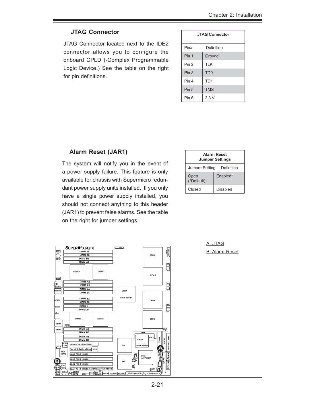
JTAG Connector located next to the IDE2 connector allows you to configure the onboard CPLD
JTAG Connector
Pin# | Defi nition | |
Pin 1 | Ground | |
Pin 2 | TLK | |
Pin 3 | TD0 | |
Pin 4 | TD1 | |
Pin 5 | TMS | |
Pin 6 | 3.3 V | |
|
|
Alarm Reset (JAR1)
The system will notify you in the event of a power supply failure. This feature is only available for chassis with Supermicro redun- dant power supply units installed. If you only have a single power supply installed, you should not connect anything to this header (JAR1) to prevent false alarms. See the table on the right for jumper settings.
Alarm Reset
Jumper Settings
Jumper Setting | Defi nition | |
Open |
| Enabled* |
(*Default) |
|
|
|
|
|
Closed |
| Disabled |
|
|
|
A. JTAG
| SUPER | ® | X6QT8 |
|
| JD1 |
|
|
|
|
|
|
| ||||
Fan7 |
|
|
| DIMM B8 |
|
|
|
|
|
|
|
|
| LE1 | CTRL | B. Alarm Reset | |
|
|
|
| DIMM A8 |
|
|
|
|
|
|
| CPU 1 |
|
| FP |
| |
SPKR |
|
|
| DIMM B7 |
|
|
|
|
|
|
|
|
|
|
|
| |
|
|
|
| DIMM A7 |
|
|
|
|
|
|
|
|
| Fan6 |
| ||
|
|
|
|
|
|
|
|
|
|
|
|
|
|
|
| ||
|
|
| UXMB4 |
|
|
| UXMB3 |
|
|
|
|
|
| Fan5 |
| ||
|
|
|
|
|
|
|
|
|
|
|
|
|
|
| |||
|
|
|
|
|
|
|
|
|
|
|
|
| CPU 2 |
|
|
|
|
Fan8 |
|
|
|
|
|
|
|
|
|
|
|
|
|
|
|
|
|
KB/ |
|
|
| DIMM A5 |
|
|
|
|
|
|
|
|
| Fan4 |
| ||
|
|
| DIMM B5 |
|
|
|
|
|
|
|
|
|
| ||||
Mouse |
|
|
|
|
|
|
|
|
|
|
|
|
|
|
| ||
|
|
|
|
|
|
|
|
|
|
|
|
|
|
|
|
| |
USB0/1 |
|
|
| DIMM A6 |
|
|
|
| E8501 |
|
|
|
| Fan3 |
| ||
|
|
| DIMM B6 |
|
|
|
|
|
|
|
|
|
|
| |||
|
|
|
|
|
|
|
|
|
|
|
|
|
|
|
| ||
|
|
|
| DIMM B2 |
|
|
|
| (North Bridge) |
|
|
|
|
|
| ||
COM1 |
|
|
|
|
|
|
|
|
|
| CPU 4 |
|
|
|
| ||
|
|
| DIMM A2 |
|
|
|
|
|
|
|
|
|
|
| |||
|
|
|
|
|
|
|
|
|
|
|
|
| Fan2 |
| |||
|
|
|
| DIMM B1 |
|
|
|
|
|
|
|
|
|
| |||
|
|
|
|
|
|
|
|
|
|
|
|
|
|
|
| ||
|
|
|
| DIMM A1 |
|
|
|
|
|
|
|
|
| Fan1 |
| ||
VGA |
|
|
|
|
|
|
|
|
|
|
|
|
|
|
| ||
|
|
|
|
|
|
|
|
|
|
|
|
|
|
|
|
| |
|
|
| UXMB2 |
|
|
| UXMB1 |
|
|
|
| CPU 3 |
|
|
|
| |
GLAN1 |
|
|
|
|
|
|
|
|
|
|
|
|
|
|
|
|
|
| Fan9 |
|
|
|
|
|
|
|
|
|
|
|
|
|
|
| |
GLAN2 |
|
|
| DIMM A3 |
|
|
|
|
|
|
|
|
| JWF2 |
|
| |
|
|
|
|
|
|
|
|
|
|
|
|
|
|
|
|
| |
|
|
|
| DIMM B3 |
|
|
|
|
|
| IPMI |
|
|
|
|
| |
|
|
|
| DIMM A4 |
|
|
|
|
|
|
| CPLD | Floppy | #1 | PWR |
| |
|
|
|
| DIMM B4 |
|
|
|
|
| ICH5R |
| ||||||
|
|
|
|
|
|
|
|
|
|
|
|
| IDE | ATX |
| ||
| GLAN | Slot 6 |
|
|
|
| PXH | (South Bridge) |
|
| |||||||
JPL1 | CTRL |
|
|
|
|
|
|
|
|
| |||||||
|
|
|
|
|
|
|
|
|
|
|
| ||||||
|
|
|
|
|
|
|
|
|
|
|
| SCSI |
| JOH1 | JTG | PW |
|
| VGA |
| Slot 5 | BIOS |
|
|
|
|
| A | Pin24- |
| |||||
B | CTRL |
| Slot 4 |
|
|
|
|
| J27 |
|
|
| IDE |
| |||
|
| Slot 2 |
|
|
|
|
| JPA1 | AIC7902W | WD1 |
| ||||||
|
|
| Slot 3 |
|
|
|
|
| DA2 |
|
|
| #2 |
|
| ||
|
|
|
|
|
|
|
|
|
| PXH | DA1 |
|
| B |
|
|
|
JAR1 | S I/O |
| JBT1 |
|
|
|
|
|
|
| JPA2 |
|
| PSSM |
|
| |
|
|
|
|
| JRB1 | JL1 WOR1 USB2/3 |
|
|
|
| JWF1 | JPA3 |
| ||||
J3P1 |
|
| COM2 |
| SMB |
| SCSI Channel A | SCSI Channel B |
| ||||||||
|
|
| Slot 1 | 100MHz (*: ZCR/Green Slot: X6QT8) |
|
|
| JFSB1 |
|
|
|
| |||||
JP13 | Battery | JPG1 |
| WOL1 |
|
|
|
|
|
|
|
|
|
|
| ||
|
|
|
|
|
|
|
|
|
|
|
|
|
|
| |||