![]()
![]()
![]() X6QT8/X6QTE+ User's Manual
X6QT8/X6QTE+ User's Manual
2-6 Jumper Settings
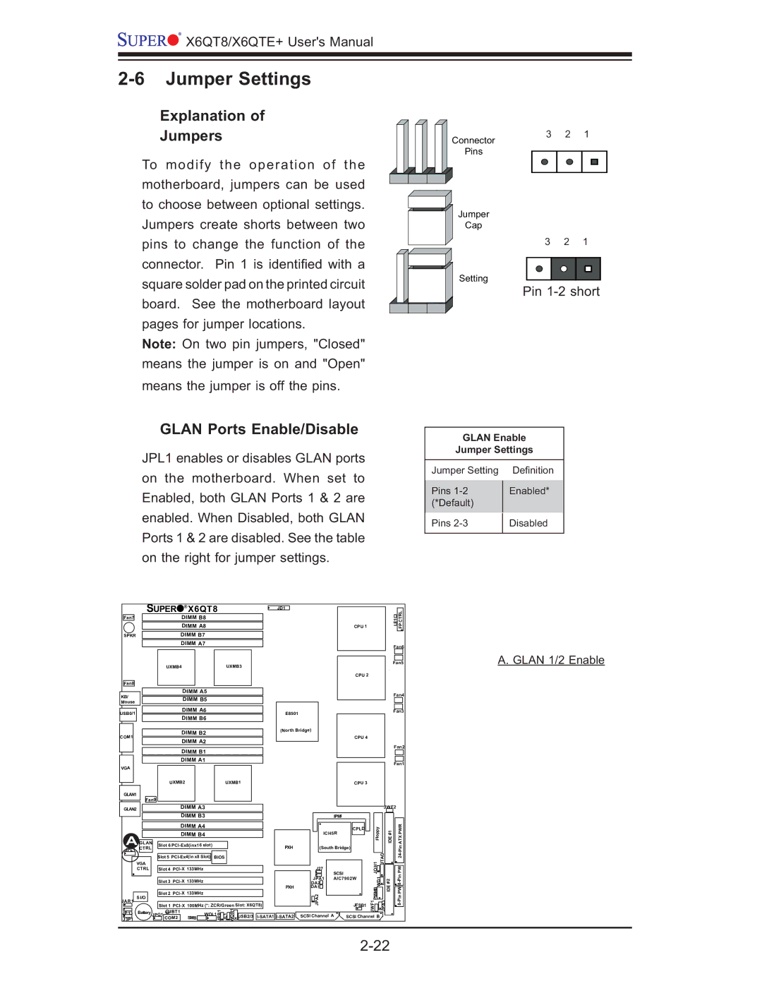
Explanation of
Jumpers
To modify the operation of the motherboard, jumpers can be used to choose between optional settings. Jumpers create shorts between two
Connector
Pins
Jumper
Cap
3 2 1
pins to change the function of the connector. Pin 1 is identifi ed with a square solder pad on the printed circuit board. See the motherboard layout pages for jumper locations.
Note: On two pin jumpers, "Closed" means the jumper is on and "Open" means the jumper is off the pins.
GLAN Ports Enable/Disable
JPL1 enables or disables GLAN ports on the motherboard. When set to Enabled, both GLAN Ports 1 & 2 are enabled. When Disabled, both GLAN Ports 1 & 2 are disabled. See the table on the right for jumper settings.
3 2 1
Setting
Pin 1-2 short
GLAN Enable
Jumper Settings
Jumper Setting | Defi nition | |
Pins | Enabled* | |
(*Default) |
| |
Pins | Disabled | |
|
|
| SUPER | ® | X6QT8 |
|
| JD1 |
|
|
|
|
|
|
|
| ||||
Fan7 |
|
|
| DIMM B8 |
|
|
|
|
|
|
|
|
|
| LE1 | CTRL |
| |
|
|
|
|
|
|
|
|
|
|
|
|
|
|
| ||||
|
|
|
| DIMM A8 |
|
|
|
|
|
|
| CPU 1 |
|
| FP |
| ||
|
|
|
|
|
|
|
|
|
|
|
|
|
|
| ||||
SPKR |
|
|
| DIMM B7 |
|
|
|
|
|
|
|
|
|
|
|
|
| |
|
|
|
| DIMM A7 |
|
|
|
|
|
|
|
|
|
| Fan6 |
| ||
|
|
|
|
|
|
|
|
|
|
|
|
|
|
|
|
| ||
|
|
| UXMB4 |
|
|
| UXMB3 |
|
|
|
|
|
|
| Fan5 | A. GLAN 1/2 Enable | ||
|
|
|
|
|
|
|
|
|
|
|
|
| CPU 2 |
|
|
|
|
|
Fan8 |
|
|
|
|
|
|
|
|
|
|
|
|
|
|
|
|
|
|
KB/ |
|
|
| DIMM A5 |
|
|
|
|
|
|
|
|
|
| Fan4 |
| ||
|
|
| DIMM B5 |
|
|
|
|
|
|
|
|
|
|
| ||||
|
|
|
|
|
|
|
|
|
|
|
|
|
|
|
| |||
Mouse |
|
|
|
|
|
|
|
|
|
|
|
|
|
|
|
| ||
|
|
|
|
|
|
|
|
|
|
|
|
|
|
|
|
|
| |
USB0/1 |
|
|
| DIMM A6 |
|
|
|
| E8501 |
|
|
|
|
| Fan3 |
| ||
|
|
| DIMM B6 |
|
|
|
|
|
|
|
|
|
|
|
| |||
|
|
|
|
|
|
|
|
|
|
|
|
|
|
|
|
| ||
|
|
|
| DIMM B2 |
|
|
|
| (North Bridge) |
|
|
|
|
|
|
| ||
COM1 |
|
|
|
|
|
|
|
|
|
| CPU 4 |
|
|
|
|
| ||
|
|
| DIMM A2 |
|
|
|
|
|
|
|
|
|
|
|
| |||
|
|
|
|
|
|
|
|
|
|
|
|
|
| Fan2 |
| |||
|
|
|
| DIMM B1 |
|
|
|
|
|
|
|
|
|
|
| |||
|
|
|
|
|
|
|
|
|
|
|
|
|
|
|
|
| ||
|
|
|
| DIMM A1 |
|
|
|
|
|
|
|
|
|
| Fan1 |
| ||
VGA |
|
|
|
|
|
|
|
|
|
|
|
|
|
|
|
| ||
|
|
|
|
|
|
|
|
|
|
|
|
|
|
|
|
|
| |
|
|
| UXMB2 |
|
|
| UXMB1 |
|
|
|
| CPU 3 |
|
|
|
|
| |
GLAN1 |
|
|
|
|
|
|
|
|
|
|
|
|
|
|
|
|
|
|
| Fan9 |
|
|
|
|
|
|
|
|
|
|
|
|
|
|
|
| |
GLAN2 |
|
|
| DIMM A3 |
|
|
|
|
|
|
|
|
| JWF2 |
|
| ||
|
|
|
| DIMM B3 |
|
|
|
|
|
| IPMI |
|
|
|
|
|
| |
|
|
|
| DIMM A4 |
|
|
|
|
|
|
| CPLD | Floppy | #1 |
| PWR |
| |
|
|
|
| DIMM B4 |
|
|
|
|
| ICH5R |
|
| ||||||
|
|
|
|
|
|
|
|
|
|
|
|
| IDE |
| ATX |
| ||
| GLAN |
|
|
|
|
|
|
|
|
|
|
|
|
|
| |||
A CTRL |
| Slot 6 |
|
|
|
| PXH | (South Bridge) |
|
|
|
|
| |||||
JPL1 |
|
|
|
|
|
|
|
|
|
|
| SCSI |
| JOH1 | JTAG |
| PW |
|
|
|
| Slot 5 | BIOS |
|
|
|
|
|
| ||||||||
|
|
|
|
|
|
|
|
|
|
| Pin24- |
| ||||||
| VGA |
|
|
|
|
|
|
|
|
| J27 |
|
|
|
|
|
|
|
| CTRL |
| Slot 4 |
|
|
|
|
|
|
| WD1 |
|
|
| ||||
|
|
|
|
|
|
|
|
|
|
| DA2 | AIC7902W | #2 |
|
| |||
|
|
| Slot 3 |
|
|
|
|
| JPA1 |
|
|
|
|
| ||||
|
|
|
|
|
|
|
|
|
|
|
| IDE |
|
|
| |||
|
|
|
|
|
|
|
|
|
| PXH | DA1 |
|
| PSSMB |
| PW |
| |
| S I/O |
| Slot 2 | 133MHz |
|
|
|
|
| JPA2 |
|
|
|
|
| |||
JAR1 |
|
| JBT1 |
|
|
| JRB1 | JL1 WOR1 USB2/3 |
|
|
|
| JWF1 | JPA3 |
|
| ||
J3P1 |
|
| COM2 |
| SMB |
| SCSI Channel A | SCSI Channel B |
|
| ||||||||
|
|
| Slot 1 | 100MHz (*: ZCR/Green Slot: X6QT8) |
|
|
| JFSB1 |
|
|
|
|
| |||||
JP13 | Battery | JPG1 |
| WOL1 |
|
|
|
|
|
|
|
|
|
|
|
| ||
|
|
|
|
|
|
|
|
|
|
|
|
|
|
|
| |||