![]()
![]()
![]() X6QT8/X6QTE+ User's Manual
X6QT8/X6QTE+ User's Manual
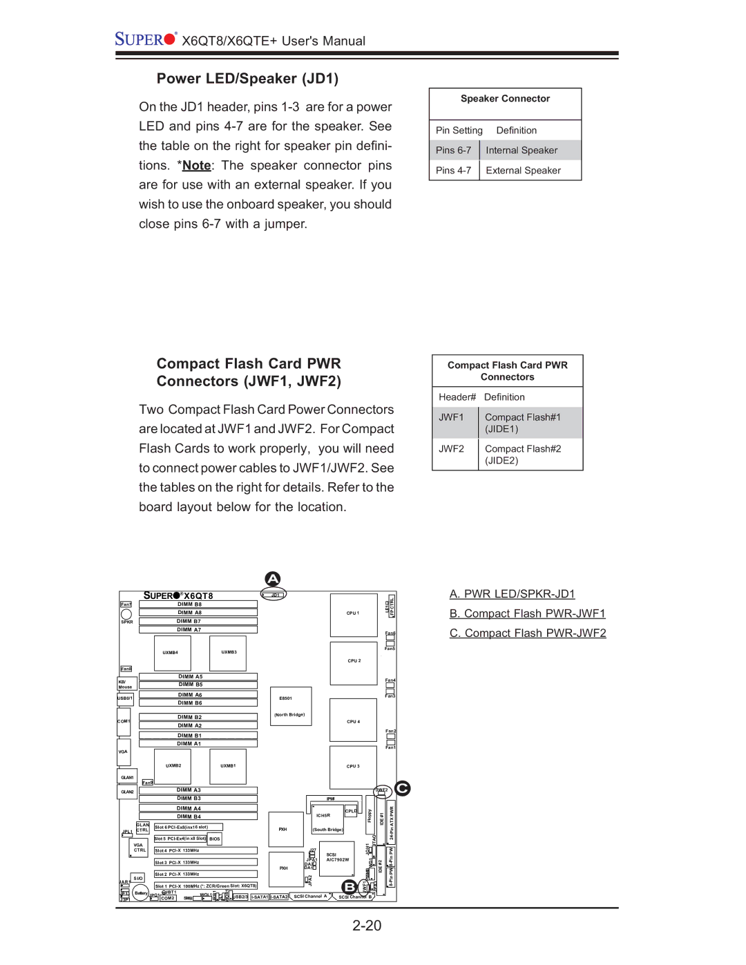
Power LED/Speaker (JD1)
On the JD1 header, pins
Compact Flash Card PWR
Connectors (JWF1, JWF2)
Two Compact Flash Card Power Connectors are located at JWF1 and JWF2. For Compact Flash Cards to work properly, you will need to connect power cables to JWF1/JWF2. See the tables on the right for details. Refer to the board layout below for the location.
Speaker Connector
Pin Setting Defi nition
Pins
Pins
Compact Flash Card PWR
Connectors
Header# |
| Defi nition |
JWF1 |
| Compact Flash#1 |
| ||
|
| (JIDE1) |
JWF2 |
| Compact Flash#2 |
| ||
|
| (JIDE2) |
|
|
|
| SUPER |
|
|
|
|
| A |
|
|
|
|
|
|
|
|
| A. PWR | |||
| ® | X6QT8 |
|
| JD1 |
|
|
|
|
|
|
|
|
| ||||||
|
|
|
|
|
|
|
|
|
|
|
|
|
|
|
|
| CTRL |
|
| |
Fan7 |
|
|
| DIMM B8 |
|
|
|
|
|
|
|
|
|
|
| LE1 |
| B. Compact Flash | ||
|
|
|
|
|
|
|
|
|
|
|
|
|
|
|
| |||||
|
|
|
| DIMM A8 |
|
|
|
|
|
|
| CPU 1 |
|
| FP |
| ||||
|
|
|
|
|
|
|
|
|
|
|
|
|
|
| ||||||
SPKR |
|
|
| DIMM B7 |
|
|
|
|
|
|
|
|
|
|
|
|
|
|
| |
|
|
|
| DIMM A7 |
|
|
|
|
|
|
|
|
|
|
| Fan6 |
| C. Compact Flash | ||
|
|
|
|
|
|
|
|
|
|
|
|
|
|
|
|
|
| |||
|
|
| UXMB4 |
|
|
| UXMB3 |
|
|
|
|
|
|
|
| Fan5 |
|
| ||
|
|
|
|
|
|
|
|
|
|
|
|
|
|
|
|
|
| |||
|
|
|
|
|
|
|
|
|
|
|
|
| CPU 2 |
|
|
|
|
|
| |
Fan8 |
|
|
|
|
|
|
|
|
|
|
|
|
|
|
|
|
|
|
|
|
KB/ |
|
|
| DIMM A5 |
|
|
|
|
|
|
|
|
|
|
| Fan4 |
|
| ||
|
|
| DIMM B5 |
|
|
|
|
|
|
|
|
|
|
|
|
| ||||
|
|
|
|
|
|
|
|
|
|
|
|
|
|
|
|
|
| |||
Mouse |
|
|
|
|
|
|
|
|
|
|
|
|
|
|
|
|
|
| ||
|
|
|
|
|
|
|
|
|
|
|
|
|
|
|
|
|
|
|
| |
USB0/1 |
|
|
| DIMM A6 |
|
|
|
| E8501 |
|
|
|
|
|
| Fan3 |
|
| ||
|
|
| DIMM B6 |
|
|
|
|
|
|
|
|
|
|
|
|
|
| |||
|
|
|
|
|
|
|
|
|
|
|
|
|
|
|
|
|
|
| ||
|
|
|
| DIMM B2 |
|
|
|
| (North Bridge) |
|
|
|
|
|
|
|
|
| ||
COM1 |
|
|
|
|
|
|
|
|
|
| CPU 4 |
|
|
|
|
|
| |||
|
|
| DIMM A2 |
|
|
|
|
|
|
|
|
|
|
|
|
| ||||
|
|
|
|
|
|
|
|
|
|
|
|
|
|
| Fan2 |
| ||||
|
|
|
| DIMM B1 |
|
|
|
|
|
|
|
|
|
|
|
| ||||
|
|
|
|
|
|
|
|
|
|
|
|
|
|
|
|
|
|
| ||
|
|
|
| DIMM A1 |
|
|
|
|
|
|
|
|
|
|
| Fan1 |
|
| ||
VGA |
|
|
|
|
|
|
|
|
|
|
|
|
|
|
|
|
|
| ||
|
|
|
|
|
|
|
|
|
|
|
|
|
|
|
|
|
|
|
| |
|
|
| UXMB2 |
|
|
| UXMB1 |
|
|
|
| CPU 3 |
|
|
|
|
|
| ||
GLAN1 |
|
|
|
|
|
|
|
|
|
|
|
|
|
|
|
|
|
| C |
|
| Fan9 |
|
|
|
|
|
|
|
|
|
|
|
|
|
|
|
|
| ||
GLAN2 |
|
|
| DIMM A3 |
|
|
|
|
|
|
|
|
|
| JWF2 |
|
| |||
|
|
| DIMM B3 |
|
|
|
|
|
| IPMI |
|
|
|
|
|
|
| |||
|
|
|
|
|
|
|
|
|
|
|
|
|
|
|
|
|
| |||
|
|
|
| DIMM A4 |
|
|
|
|
|
|
| CPLD | Floppy | #1 |
| PWR |
|
| ||
|
|
|
| DIMM B4 |
|
|
|
|
| ICH5R |
|
|
| |||||||
|
|
|
|
|
|
|
|
|
|
|
|
|
| IDE |
| ATX |
|
| ||
| GLAN | Slot 6 |
|
|
|
| PXH | (South Bridge) |
|
|
|
|
| |||||||
JPL1 | CTRL |
|
|
|
|
|
|
|
|
|
|
|
| |||||||
|
|
|
|
|
|
|
|
|
|
|
|
|
|
| ||||||
|
|
|
|
|
|
|
|
|
|
| SCSI |
|
| JOH1 | JTAG |
| PW |
|
| |
|
|
| Slot 5 | BIOS |
|
|
|
|
|
|
|
| ||||||||
|
|
|
|
|
|
|
|
|
|
|
| Pin24- |
|
| ||||||
| VGA |
|
|
|
|
|
|
|
|
| J27 |
|
|
|
|
|
|
|
|
|
| CTRL |
| Slot 4 |
|
|
|
|
|
|
|
| WD1 |
|
|
|
| ||||
|
|
|
|
|
|
|
|
|
|
| DA2 | AIC7902W |
| #2 |
|
|
| |||
|
|
| Slot 3 |
|
|
|
|
| JPA1 |
|
|
|
|
|
|
| ||||
|
|
|
|
|
|
|
|
|
|
|
|
| IDE |
|
|
|
| |||
|
|
|
|
|
|
|
|
|
| PXH | DA1 |
|
|
| PSSMB |
| PW |
|
| |
| S I/O |
| Slot 2 | 133MHz |
|
|
|
|
|
|
|
|
|
|
|
|
| |||
JAR1 |
|
| COM2 |
| SMB |
| JRB1 | JL1 WOR1 USB2/3 | SCSI Channel A | SCSI Channel B | JPA3 |
|
|
| ||||||
J3P1 |
|
|
|
|
|
|
| |||||||||||||
|
|
| Slot 1 | 100MHz (*: ZCR/Green Slot: X6QT8) |
| JPA2 |
| JFS | 1 | JWF1 |
|
|
|
|
| |||||
JP13 | Battery | JPG1 JBT1 |
| WOL1 |
|
|
|
|
| B |
|
|
|
|
|
| ||||
|
|
|
|
|
|
|
|
|
|
|
|
|
|
|
|
| ||||