![]()
![]()
![]() X6QT8/X6QTE+ User's Manual
X6QT8/X6QTE+ User's Manual
B. Front Control Panel
Front Control Panel
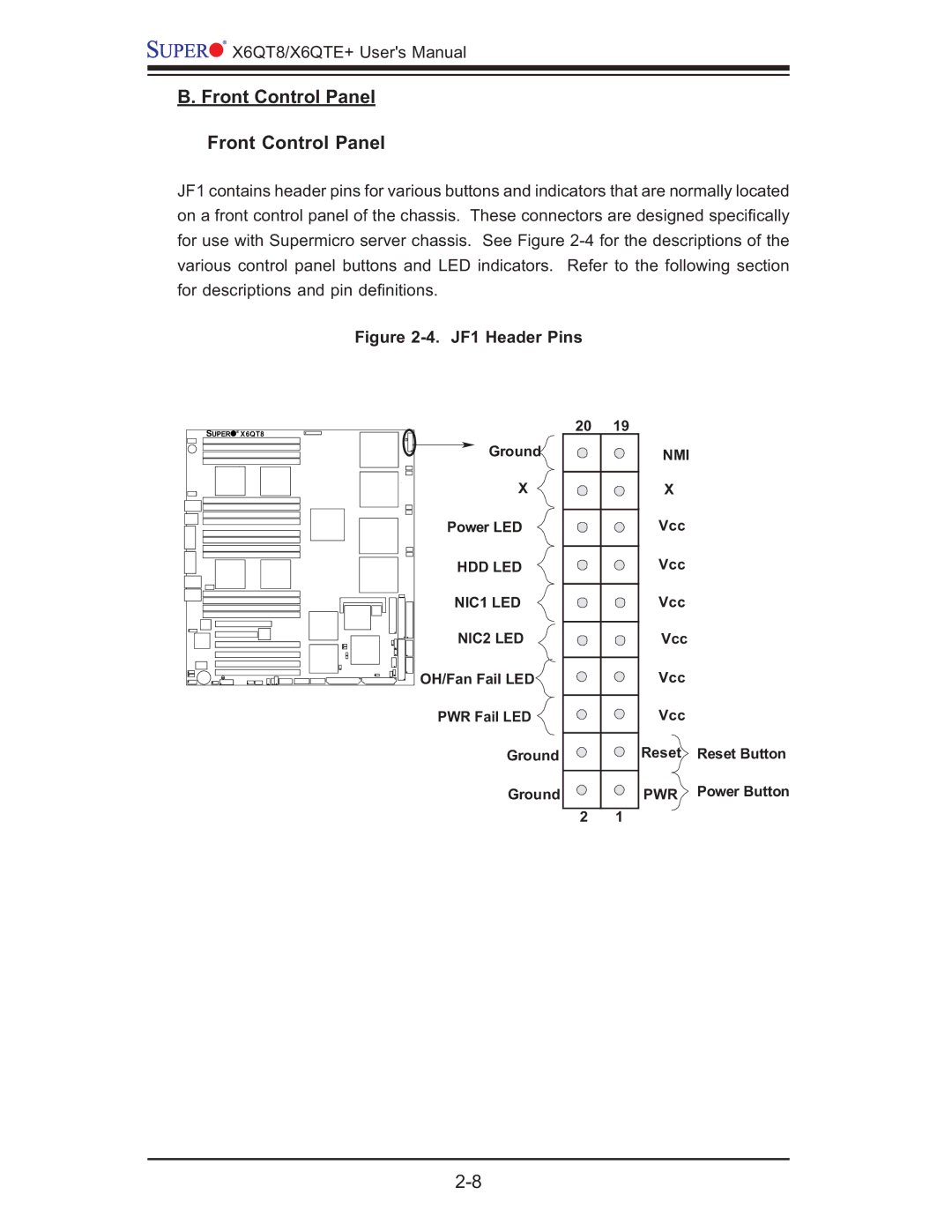
JF1 contains header pins for various buttons and indicators that are normally located on a front control panel of the chassis. These connectors are designed specifi cally for use with Supermicro server chassis. See Figure
Figure 2-4. JF1 Header Pins
SUPER
® X6QT8
Ground
X
Power LED
HDD LED
NIC1 LED
NIC2 LED
OH/Fan Fail LED
PWR Fail LED
Ground
Ground
20 | 19 |
| NMI |
| X |
| Vcc |
Vcc
Vcc
Vcc
Vcc
Vcc
Reset Reset Button
PWR Power Button
2 1