![]()
![]()
![]() X6QT8/X6QTE+ User's Manual
X6QT8/X6QTE+ User's Manual
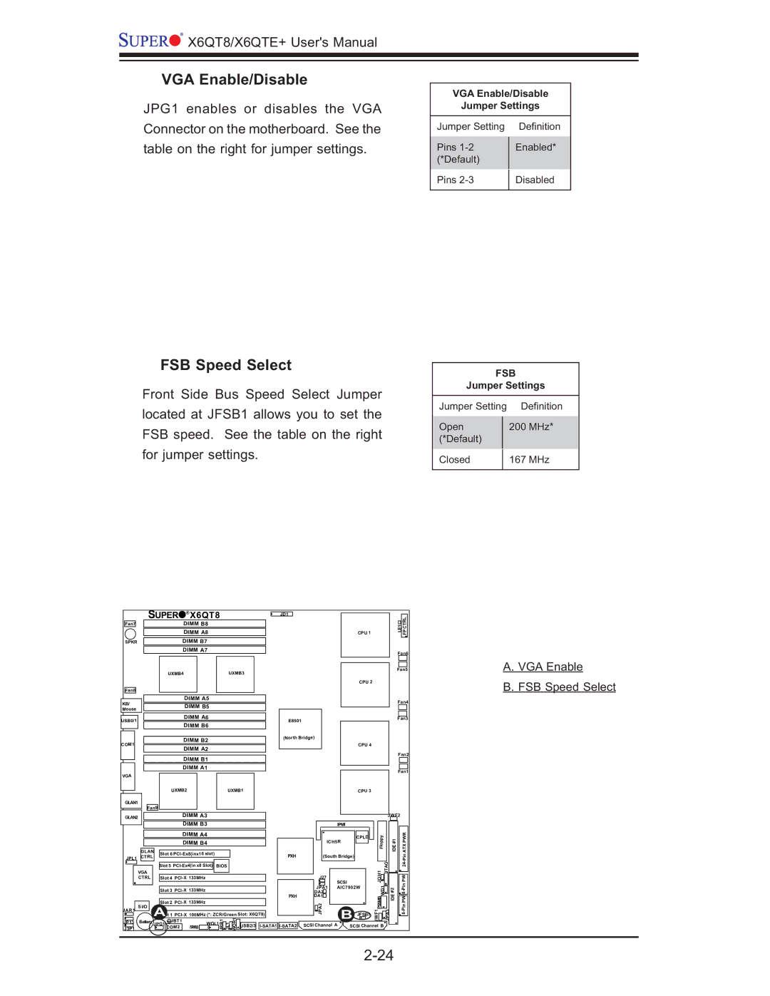
VGA Enable/Disable
JPG1 enables or disables the VGA Connector on the motherboard. See the table on the right for jumper settings.
FSB Speed Select
Front Side Bus Speed Select Jumper located at JFSB1 allows you to set the FSB speed. See the table on the right for jumper settings.
VGA Enable/Disable
Jumper Settings
Jumper Setting | Defi nition | |
Pins | Enabled* | |
(*Default) |
| |
Pins | Disabled | |
|
|
FSB
Jumper Settings
Jumper Setting | Defi nition | |
Open |
| 200 MHz* |
(*Default) |
|
|
|
|
|
Closed |
| 167 MHz |
|
|
|
| SUPER | ® | X6QT8 |
|
| JD1 |
|
|
|
|
|
|
|
|
| ||||
Fan7 |
|
|
| DIMM B8 |
|
|
|
|
|
|
|
|
|
|
| LE1 | CTRL |
| |
|
|
|
|
|
|
|
|
|
|
|
|
|
|
|
| ||||
|
|
|
| DIMM A8 |
|
|
|
|
|
|
|
| CPU 1 |
|
| FP |
| ||
|
|
|
|
|
|
|
|
|
|
|
|
|
|
|
| ||||
SPKR |
|
|
| DIMM B7 |
|
|
|
|
|
|
|
|
|
|
|
|
|
| |
|
|
|
| DIMM A7 |
|
|
|
|
|
|
|
|
|
|
| Fan6 |
| ||
|
|
|
|
|
|
|
|
|
|
|
|
|
|
|
|
|
| ||
|
|
| UXMB4 |
|
|
| UXMB3 |
|
|
|
|
|
|
|
| Fan5 | A. VGA Enable | ||
|
|
|
|
|
|
|
|
|
|
|
|
|
| CPU 2 |
|
|
|
| B. FSB Speed Select |
Fan8 |
|
|
|
|
|
|
|
|
|
|
|
|
|
|
|
|
|
| |
KB/ |
|
|
| DIMM A5 |
|
|
|
|
|
|
|
|
|
|
| Fan4 |
| ||
|
|
| DIMM B5 |
|
|
|
|
|
|
|
|
|
|
|
| ||||
|
|
|
|
|
|
|
|
|
|
|
|
|
|
|
|
| |||
Mouse |
|
|
|
|
|
|
|
|
|
|
|
|
|
|
|
|
| ||
|
|
|
|
|
|
|
|
|
|
|
|
|
|
|
|
|
|
| |
USB0/1 |
|
|
| DIMM A6 |
|
|
|
| E8501 |
|
|
|
|
|
| Fan3 |
| ||
|
|
| DIMM B6 |
|
|
|
|
|
|
|
|
|
|
|
|
| |||
|
|
|
|
|
|
|
|
|
|
|
|
|
|
|
|
|
| ||
|
|
|
| DIMM B2 |
|
|
|
| (North Bridge) |
|
|
|
|
|
|
|
| ||
COM1 |
|
|
|
|
|
|
|
|
|
|
| CPU 4 |
|
|
|
|
| ||
|
|
| DIMM A2 |
|
|
|
|
|
|
|
|
|
|
|
|
| |||
|
|
|
|
|
|
|
|
|
|
|
|
|
|
| Fan2 |
| |||
|
|
|
| DIMM B1 |
|
|
|
|
|
|
|
|
|
|
|
| |||
|
|
|
|
|
|
|
|
|
|
|
|
|
|
|
|
|
| ||
|
|
|
| DIMM A1 |
|
|
|
|
|
|
|
|
|
|
| Fan1 |
| ||
VGA |
|
|
|
|
|
|
|
|
|
|
|
|
|
|
|
|
| ||
|
|
|
|
|
|
|
|
|
|
|
|
|
|
|
|
|
|
| |
|
|
| UXMB2 |
|
|
| UXMB1 |
|
|
|
|
| CPU 3 |
|
|
|
|
| |
GLAN1 |
|
|
|
|
|
|
|
|
|
|
|
|
|
|
|
|
|
|
|
| Fan9 |
|
|
|
|
|
|
|
|
|
|
|
|
|
|
|
|
| |
GLAN2 |
|
|
| DIMM A3 |
|
|
|
|
|
|
|
|
|
| JWF2 |
|
| ||
|
|
|
| DIMM B3 |
|
|
|
|
|
| IPMI |
|
|
|
|
|
|
| |
|
|
|
| DIMM A4 |
|
|
|
|
|
|
|
| CPLD | Floppy | #1 |
| PWR |
| |
|
|
|
| DIMM B4 |
|
|
|
|
| ICH5R |
|
|
| ||||||
|
|
|
|
|
|
|
|
|
|
|
|
|
| IDE |
| ATX |
| ||
| GLAN | Slot 6 |
|
|
|
| PXH | (South Bridge) |
|
|
|
| |||||||
JPL1 | CTRL |
|
|
|
|
|
|
|
|
|
|
| |||||||
|
|
|
|
|
|
|
|
|
|
|
|
|
| ||||||
|
|
|
|
|
|
|
|
|
|
| SCSI |
|
| JOH1 | JTAG |
| PW |
| |
|
|
| Slot 5 | BIOS |
|
|
|
|
|
|
| ||||||||
|
|
|
|
|
|
|
|
|
|
|
| Pin24- |
| ||||||
| VGA |
|
|
|
|
|
|
|
|
| J27 |
|
|
|
|
|
|
|
|
| CTRL |
| Slot 4 |
|
|
|
|
|
|
|
| WD1 |
|
|
| ||||
|
|
|
|
|
|
|
|
|
|
| DA2 | AIC7902W | #2 |
|
| ||||
|
|
| Slot 3 |
|
|
|
|
| JPA1 |
|
|
|
|
| |||||
|
|
|
|
|
|
|
|
|
|
|
|
| IDE |
|
|
| |||
|
|
|
|
|
|
|
|
|
| PXH | DA1 |
|
|
| PSSMB |
| PW |
| |
| S I/O |
| Slot 2 | 133MHz |
|
|
|
|
| JPA2 | B |
|
|
|
| ||||
JAR1 |
|
| JBT1 |
|
|
| JRB1 | JL1 WOR1 USB2/3 |
|
|
| JWF1 | JPA3 |
|
| ||||
J3P1 |
|
| COM2 |
| SMB |
| SCSI Channel A | SCSI Channel B |
|
| |||||||||
JP13 | Battery | ASlot 1 | 100MHz (*: ZCR/Green Slot: X6QT8) |
|
|
|
| JFSB1 |
|
|
|
|
| ||||||
JPG1 |
| WOL1 |
|
|
|
|
|
|
|
|
|
|
|
|
| ||||
|
|
|
|
|
|
|
|
|
|
|
|
|
|
|
|
| |||