Chapter 2: Installation
2-7 Onboard Indicators
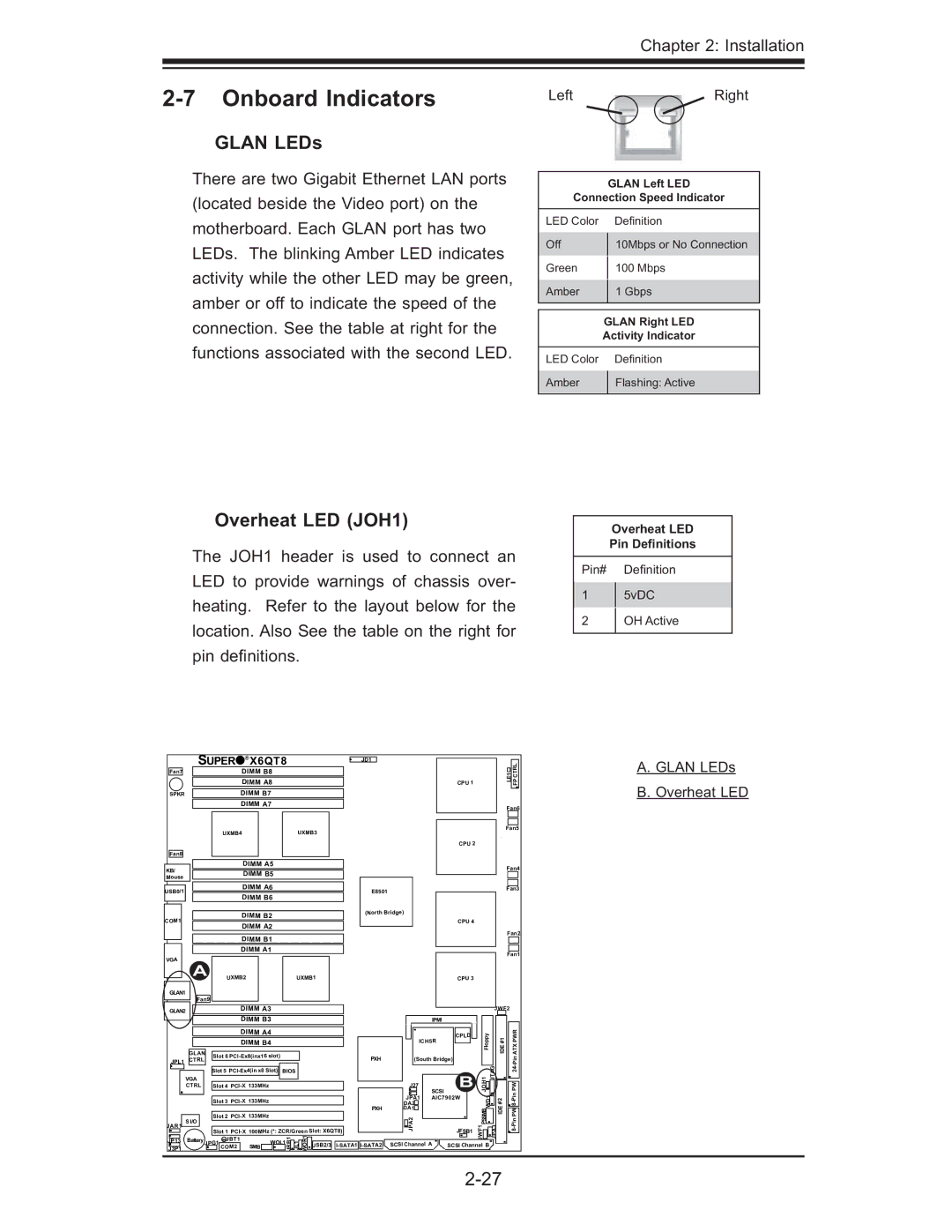
GLAN LEDs
There are two Gigabit Ethernet LAN ports (located beside the Video port) on the motherboard. Each GLAN port has two LEDs. The blinking Amber LED indicates activity while the other LED may be green, amber or off to indicate the speed of the connection. See the table at right for the functions associated with the second LED.
Overheat LED (JOH1)
The JOH1 header is used to connect an LED to provide warnings of chassis over- heating. Refer to the layout below for the location. Also See the table on the right for pin defi nitions.
LeftRight
GLAN Left LED
Connection Speed Indicator
LED Color |
| Defi nition |
Off |
| 10Mbps or No Connection |
| ||
Green |
| 100 Mbps |
| ||
Amber |
| 1 Gbps |
| ||
|
|
|
|
| |
| GLAN Right LED | |
| Activity Indicator | |
|
|
|
LED Color |
| Defi nition |
Amber |
| Flashing: Active |
| ||
|
|
|
Overheat LED
Pin Definitions
Pin# Defi nition
15vDC
2OH Active
| SUPER | ® | X6QT8 |
|
| JD1 |
|
|
|
|
|
|
| A. GLAN LEDs | ||||
Fan7 |
|
|
| DIMM B8 |
|
|
|
|
|
|
|
|
|
| LE1 | CTRL | ||
|
|
|
| DIMM A8 |
|
|
|
|
|
|
| CPU 1 |
|
| FP | B. Overheat LED | ||
|
|
|
|
|
|
|
|
|
|
|
|
|
| |||||
SPKR |
|
|
| DIMM B7 |
|
|
|
|
|
|
|
|
|
|
|
| ||
|
|
|
| DIMM A7 |
|
|
|
|
|
|
|
|
|
| Fan6 |
| ||
|
|
|
|
|
|
|
|
|
|
|
|
|
|
|
|
| ||
|
| UXMB4 |
|
|
| UXMB3 |
|
|
|
|
|
|
| Fan5 |
| |||
|
|
|
|
|
|
|
|
|
|
|
|
|
|
| ||||
|
|
|
|
|
|
|
|
|
|
|
|
| CPU 2 |
|
|
|
|
|
Fan8 |
|
|
|
|
|
|
|
|
|
|
|
|
|
|
|
|
|
|
KB/ |
|
|
| DIMM A5 |
|
|
|
|
|
|
|
|
|
| Fan4 |
| ||
|
|
| DIMM B5 |
|
|
|
|
|
|
|
|
|
|
| ||||
|
|
|
|
|
|
|
|
|
|
|
|
|
|
|
| |||
Mouse |
|
|
|
|
|
|
|
|
|
|
|
|
|
|
|
| ||
|
|
|
|
|
|
|
|
|
|
|
|
|
|
|
|
|
| |
USB0/1 |
|
|
| DIMM A6 |
|
|
|
| E8501 |
|
|
|
|
| Fan3 |
| ||
|
|
| DIMM B6 |
|
|
|
|
|
|
|
|
|
|
|
| |||
|
|
|
|
|
|
|
|
|
|
|
|
|
|
|
|
| ||
|
|
|
| DIMM B2 |
|
|
|
| (North Bridge) |
|
|
|
|
|
|
| ||
COM1 |
|
|
|
|
|
|
|
|
|
| CPU 4 |
|
|
|
|
| ||
|
|
| DIMM A2 |
|
|
|
|
|
|
|
|
|
|
|
| |||
|
|
|
|
|
|
|
|
|
|
|
|
|
| Fan2 |
| |||
|
|
|
| DIMM B1 |
|
|
|
|
|
|
|
|
|
|
| |||
|
|
|
|
|
|
|
|
|
|
|
|
|
|
|
|
| ||
|
|
|
| DIMM A1 |
|
|
|
|
|
|
|
|
|
| Fan1 |
| ||
VGA |
|
|
|
|
|
|
|
|
|
|
|
|
|
|
|
| ||
A |
|
|
|
|
|
|
|
|
|
|
|
|
|
|
|
|
| |
| UXMB2 |
|
|
| UXMB1 |
|
|
|
| CPU 3 |
|
|
|
|
| |||
GLAN1 |
|
|
|
|
|
|
|
|
|
|
|
|
|
|
|
|
|
|
| Fan9 |
|
|
|
|
|
|
|
|
|
|
|
|
|
|
|
|
|
GLAN2 |
|
|
| DIMM A3 |
|
|
|
|
|
|
|
|
| JWF2 |
|
| ||
|
|
|
| DIMM B3 |
|
|
|
|
|
| IPMI |
|
|
|
|
|
| |
|
|
|
| DIMM A4 |
|
|
|
|
|
|
| CPLD | Floppy | #1 |
| PWR |
| |
|
|
|
| DIMM B4 |
|
|
|
|
| ICH5R |
|
| ||||||
|
|
|
|
|
|
|
|
|
|
|
|
| IDE |
| ATX |
| ||
| GLAN | Slot 6 |
|
|
|
| PXH | (South Bridge) |
|
|
| |||||||
JPL1 | CTRL |
|
|
|
|
|
|
|
|
| ||||||||
|
|
|
|
|
|
|
|
|
|
|
|
| ||||||
CTRL | Slot 4 | 133MHz |
|
|
|
|
| J27 | SCSI | B | JOH1 | JTAG |
| PW |
| |||
| BIOS |
|
|
|
| |||||||||||||
|
| Slot 5 |
|
|
|
|
|
|
|
| Pin24- |
| ||||||
| VGA |
|
|
|
|
|
|
|
|
|
|
|
|
|
|
|
|
|
|
|
|
|
|
|
|
|
|
|
| DA2 | AIC7902W | WD1 | #2 |
|
| ||
|
| Slot 3 |
|
|
|
|
| JPA1 |
|
|
|
|
| |||||
|
|
|
|
|
|
|
|
|
|
| IDE |
|
|
| ||||
|
|
|
|
|
|
|
|
|
| PXH | DA1 |
|
| PSSMB |
| PW |
| |
| S I/O | Slot 2 |
|
|
|
|
| JPA2 |
|
|
|
|
| |||||
JAR1 |
| JBT1 |
|
|
| JRB1 | JL1 OR1W USB2/3 |
|
|
|
| JWF1 | JPA3 |
|
| |||
J3P1 |
| COM2 |
| SMB |
| SCSI Channel A | SCSI Channel B |
|
| |||||||||
|
| Slot 1 | 100MHz (*: ZCR/Green Slot: X6QT8) |
|
|
| JFSB1 |
|
|
|
|
| ||||||
JP13 | Battery JPG1 |
|
| WOL1 |
|
|
|
|
|
|
|
|
|
|
|
| ||
|
|
|
|
|
|
|
|
|
|
|
|
|
|
|
| |||