4 Principles of Operation
This section describes the operation of the TCM4300 in detail.
NOTE:
Timing diagrams and associated tables are contained in Section 3 of this data manual.
4.1Data Transfer
The interface to both the system digital signal processor and microcontroller is in the form of 2s complement.
4.2Receive Section
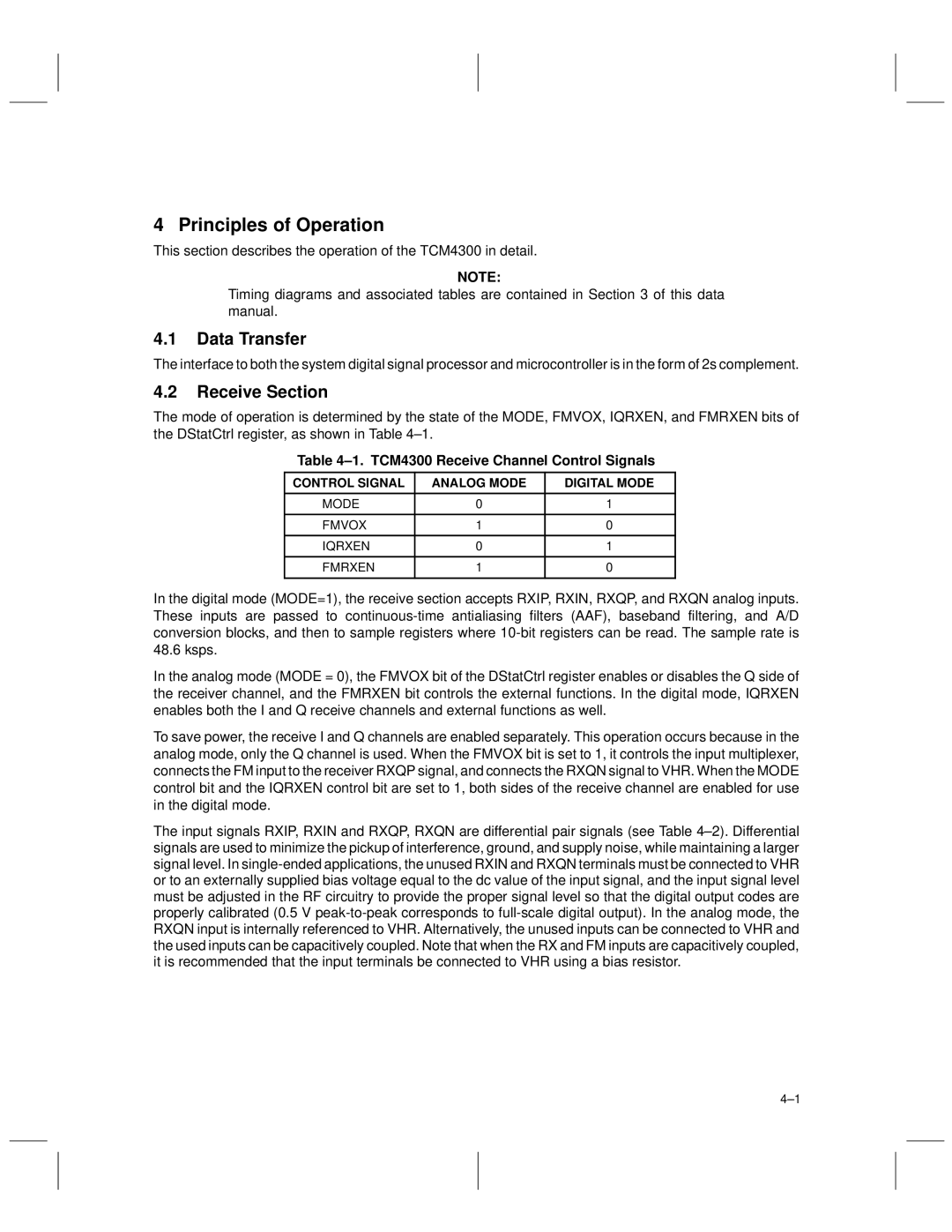
The mode of operation is determined by the state of the MODE, FMVOX, IQRXEN, and FMRXEN bits of the DStatCtrl register, as shown in Table 4±1.
Table 4±1. TCM4300 Receive Channel Control Signals
CONTROL SIGNAL | ANALOG MODE | DIGITAL MODE |
|
|
|
MODE | 0 | 1 |
|
|
|
FMVOX | 1 | 0 |
|
|
|
IQRXEN | 0 | 1 |
|
|
|
FMRXEN | 1 | 0 |
|
|
|
In the digital mode (MODE=1), the receive section accepts RXIP, RXIN, RXQP, and RXQN analog inputs. These inputs are passed to
In the analog mode (MODE = 0), the FMVOX bit of the DStatCtrl register enables or disables the Q side of the receiver channel, and the FMRXEN bit controls the external functions. In the digital mode, IQRXEN enables both the I and Q receive channels and external functions as well.
To save power, the receive I and Q channels are enabled separately. This operation occurs because in the analog mode, only the Q channel is used. When the FMVOX bit is set to 1, it controls the input multiplexer, connects the FM input to the receiver RXQP signal, and connects the RXQN signal to VHR. When the MODE control bit and the IQRXEN control bit are set to 1, both sides of the receive channel are enabled for use in the digital mode.
The input signals RXIP, RXIN and RXQP, RXQN are differential pair signals (see Table 4±2). Differential signals are used to minimize the pickup of interference, ground, and supply noise, while maintaining a larger signal level. In
4±1