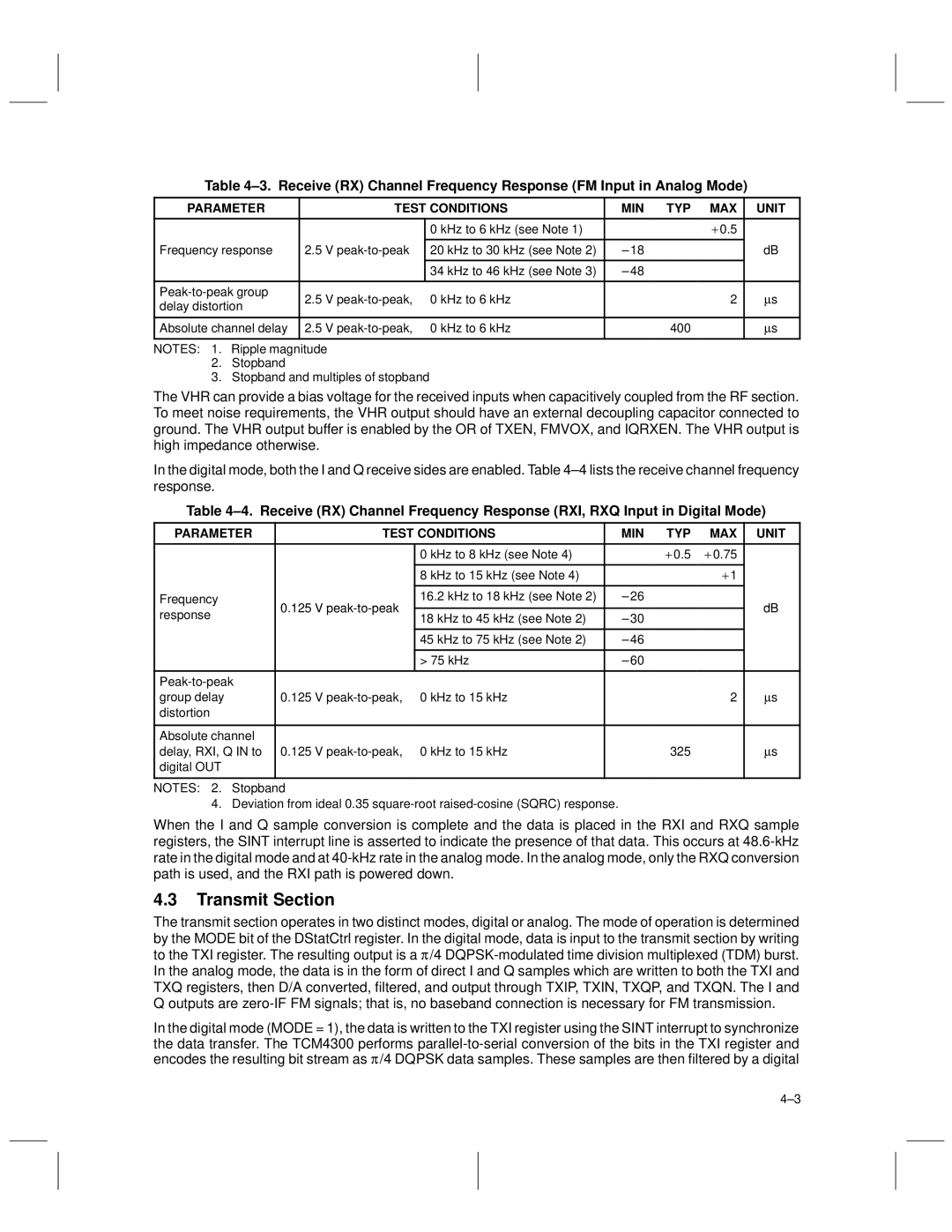
Table 4±3. Receive (RX) Channel Frequency Response (FM Input in Analog Mode)
PARAMETER |
| TEST CONDITIONS | MIN TYP MAX | UNIT | ||
|
|
|
|
|
| |
|
|
| 0 kHz to 6 kHz (see Note 1) | ± 0.5 |
| |
Frequency response | 2.5 | V |
|
| dB | |
20 kHz to 30 kHz (see Note 2) | ± 18 | |||||
|
|
|
|
|
| |
|
|
| 34 kHz to 46 kHz (see Note 3) | ± 48 |
| |
|
|
|
|
|
| |
2.5 | V | 0 kHz to 6 kHz | 2 | μs | ||
delay distortion | ||||||
|
|
|
|
| ||
|
|
|
|
|
| |
Absolute channel delay | 2.5 | V | 0 kHz to 6 kHz | 400 | μs | |
|
|
|
|
|
| |
NOTES: 1. Ripple magnitude
2.Stopband
3.Stopband and multiples of stopband
The VHR can provide a bias voltage for the received inputs when capacitively coupled from the RF section. To meet noise requirements, the VHR output should have an external decoupling capacitor connected to ground. The VHR output buffer is enabled by the OR of TXEN, FMVOX, and IQRXEN. The VHR output is high impedance otherwise.
In the digital mode, both the I and Q receive sides are enabled. Table 4±4 lists the receive channel frequency response.
Table 4±4. Receive (RX) Channel Frequency Response (RXI, RXQ Input in Digital Mode)
PARAMETER | TEST CONDITIONS | MIN TYP | MAX | UNIT | |
|
|
|
|
|
|
|
| 0 kHz to 8 kHz (see Note 4) | ± 0.5 | ± 0.75 |
|
|
|
|
|
|
|
|
| 8 kHz to 15 kHz (see Note 4) |
| ± 1 |
|
|
|
|
|
|
|
Frequency | 0.125 V | 16.2 kHz to 18 kHz (see Note 2) | ± 26 |
| dB |
response | 18 kHz to 45 kHz (see Note 2) | ± 30 |
| ||
|
|
| |||
|
|
|
| ||
|
|
|
|
|
|
|
| 45 kHz to 75 kHz (see Note 2) | ± 46 |
|
|
|
|
|
|
|
|
|
| > 75 kHz | ± 60 |
|
|
|
|
|
|
|
|
|
|
|
|
| |
group delay | 0.125 V | 0 kHz to 15 kHz |
| 2 | μs |
distortion |
|
|
|
|
|
|
|
|
|
|
|
Absolute channel |
|
|
|
|
|
delay, RXI, Q IN to | 0.125 V | 0 kHz to 15 kHz | 325 |
| μs |
digital OUT |
|
|
|
|
|
|
|
|
|
|
|
NOTES: 2. Stopband
4. Deviation from ideal 0.35
When the I and Q sample conversion is complete and the data is placed in the RXI and RXQ sample registers, the SINT interrupt line is asserted to indicate the presence of that data. This occurs at
4.3Transmit Section
The transmit section operates in two distinct modes, digital or analog. The mode of operation is determined by the MODE bit of the DStatCtrl register. In the digital mode, data is input to the transmit section by writing to the TXI register. The resulting output is a π /4
In the digital mode (MODE = 1), the data is written to the TXI register using the SINT interrupt to synchronize the data transfer. The TCM4300 performs
4±3