4.22 DSP Status and Control Registers
DIntCtrl, Clear and Send Bits: The bit names in the DIntCtrl register indicate the action to be taken when a 1 is written to the respective bit. When these bits are being read, a 1 indicates that the corresponding interrupt is pending. A 0 indicates that the interrupt is not pending. Writing a 0 to any bit has no effect. Writing a 1 to the clear bits clears the corresponding interrupt, and the interrupt terminal returns to its inactive level. Writing a 1 to the send bits causes the corresponding interrupt to go active.
DIntCtrl, SDIS: When a 1 is written to the SDIS bit, the SINT interrupt going to the DSP is disabled. The disabling and
DlntCtrl
9 | 8 | 7 | 6 | 5 | 4 ± 0 |
|
|
|
|
|
|
Clear WBD | SDIS | Reserved | |||
|
|
|
|
|
|
|
| R/W |
|
|
|
|
|
|
|
|
|
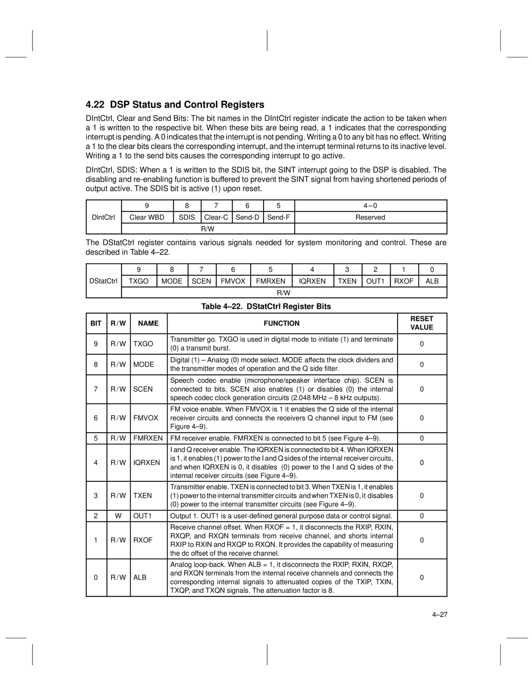
The DStatCtrl register contains various signals needed for system monitoring and control. These are described in Table 4±22.
| 9 | 8 | 7 | 6 | 5 | 4 | 3 | 2 | 1 | 0 |
DStatCtrl |
|
|
|
|
|
|
|
|
|
|
TXGO | MODE | SCEN | FMVOX | FMRXEN | IQRXEN | TXEN | OUT1 | RXOF | ALB | |
|
|
|
|
|
|
|
|
|
|
|
|
|
|
|
| R/W |
|
|
|
|
|
|
|
| Table 4±22. DStatCtrl Register Bits |
| |
BIT | R / W | NAME | FUNCTION | RESET | |
VALUE | |||||
|
|
|
| ||
|
|
|
|
| |
9 | R / W | TXGO | Transmitter go. TXGO is used in digital mode to initiate (1) and terminate | 0 | |
(0) a transmit burst. | |||||
|
|
|
| ||
|
|
|
|
| |
8 | R / W | MODE | Digital (1) ± Analog (0) mode select. MODE affects the clock dividers and | 0 | |
the transmitter modes of operation and the Q side filter. | |||||
|
|
|
| ||
|
|
|
|
| |
|
|
| Speech codec enable (microphone/speaker interface chip). SCEN is |
| |
7 | R / W | SCEN | connected to bits. SCEN also enables (1) or disables (0) the internal | 0 | |
|
|
| speech codec clock generation circuits (2.048 MHz ± 8 kHz outputs). |
| |
|
|
|
|
| |
|
|
| FM voice enable. When FMVOX is 1 it enables the Q side of the internal |
| |
6 | R / W | FMVOX | receiver circuits and connects the receivers Q channel input to FM (see | 0 | |
|
|
| Figure 4±9). |
| |
|
|
|
|
| |
5 | R / W | FMRXEN | FM receiver enable. FMRXEN is connected to bit 5 (see Figure 4±9). | 0 | |
|
|
|
|
| |
|
|
| I and Q receiver enable. The IQRXEN is connected to bit 4. When IQRXEN |
| |
4 | R / W | IQRXEN | is 1, it enables (1) power to the I and Q sides of the internal receiver circuits, | 0 | |
and when IQRXEN is 0, it disables (0) power to the I and Q sides of the | |||||
|
|
|
| ||
|
|
| internal receiver circuits (see Figure 4±9). |
| |
|
|
|
|
| |
|
|
| Transmitter enable. TXEN is connected to bit 3. When TXEN is 1, it enables |
| |
3 | R / W | TXEN | (1) power to the internal transmitter circuits and when TXEN is 0, it disables | 0 | |
|
|
| (0) power to the internal transmitter circuits (see Figure 4±9). |
| |
|
|
|
|
| |
2 | W | OUT1 | Output 1. OUT1 is a | 0 | |
|
|
|
|
| |
|
|
| Receive channel offset. When RXOF = 1, it disconnects the RXIP, RXIN, |
| |
1 | R / W | RXOF | RXQP, and RXQN terminals from receive channel, and shorts internal | 0 | |
RXIP to RXIN and RXQP to RXQN. It provides the capability of measuring | |||||
|
|
|
| ||
|
|
| the dc offset of the receive channel. |
| |
|
|
|
|
| |
|
|
| Analog |
| |
0 | R / W | ALB | and RXQN terminals from the internal receive channels and connects the | 0 | |
corresponding internal signals to attenuated copies of the TXIP, TXIN, | |||||
|
|
|
| ||
|
|
| TXQP, and TXQN signals. The attenuation factor is 8. |
| |
|
|
|
|
|
4±27