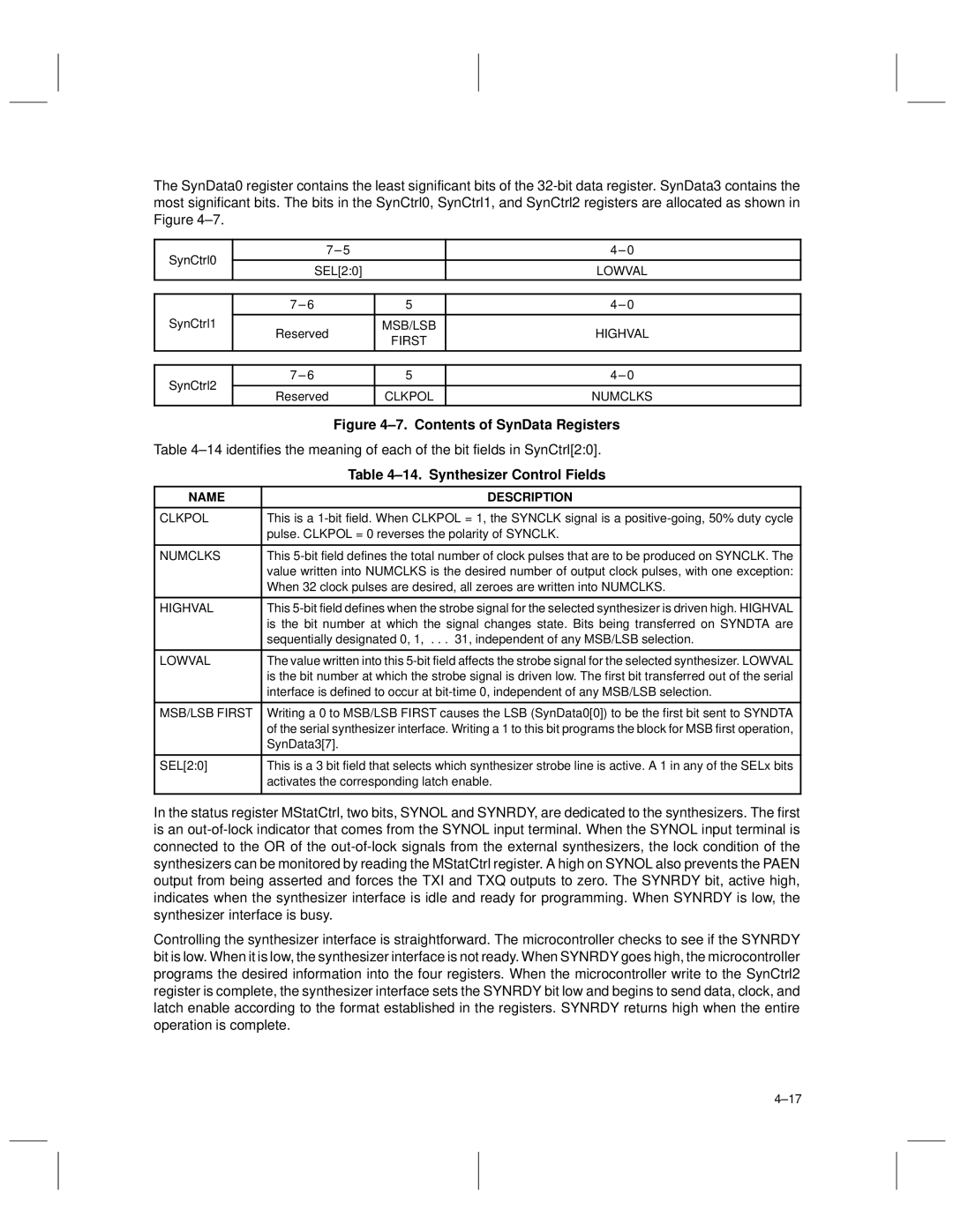
The SynData0 register contains the least significant bits of the
SynCtrl0 | 7 ± 5 |
| 4 ± 0 |
|
|
| |
SEL[2:0] |
| LOWVAL | |
|
| ||
|
|
|
|
| 7 ± 6 | 5 | 4 ± 0 |
SynCtrl1 |
|
|
|
Reserved | MSB/LSB | HIGHVAL | |
| FIRST | ||
|
|
| |
|
|
|
|
SynCtrl2
7 ± 6 | 5 | 4 ± 0 |
|
|
|
Reserved | CLKPOL | NUMCLKS |
|
|
|
| Figure 4±7. Contents of SynData Registers |
Table 4±14 identifies the meaning of each of the bit fields in SynCtrl[2:0]. | |
| Table 4±14. Synthesizer Control Fields |
|
|
NAME | DESCRIPTION |
|
|
CLKPOL | This is a |
| pulse. CLKPOL = 0 reverses the polarity of SYNCLK. |
|
|
NUMCLKS | This |
| value written into NUMCLKS is the desired number of output clock pulses, with one exception: |
| When 32 clock pulses are desired, all zeroes are written into NUMCLKS. |
|
|
HIGHVAL | This |
| is the bit number at which the signal changes state. Bits being transferred on SYNDTA are |
| sequentially designated 0, 1, . . . 31, independent of any MSB/LSB selection. |
|
|
LOWVAL | The value written into this |
| is the bit number at which the strobe signal is driven low. The first bit transferred out of the serial |
| interface is defined to occur at |
|
|
MSB/LSB FIRST | Writing a 0 to MSB/LSB FIRST causes the LSB (SynData0[0]) to be the first bit sent to SYNDTA |
| of the serial synthesizer interface. Writing a 1 to this bit programs the block for MSB first operation, |
| SynData3[7]. |
|
|
SEL[2:0] | This is a 3 bit field that selects which synthesizer strobe line is active. A 1 in any of the SELx bits |
| activates the corresponding latch enable. |
|
|
In the status register MStatCtrl, two bits, SYNOL and SYNRDY, are dedicated to the synthesizers. The first is an
Controlling the synthesizer interface is straightforward. The microcontroller checks to see if the SYNRDY bit is low. When it is low, the synthesizer interface is not ready. When SYNRDY goes high, the microcontroller programs the desired information into the four registers. When the microcontroller write to the SynCtrl2 register is complete, the synthesizer interface sets the SYNRDY bit low and begins to send data, clock, and latch enable according to the format established in the registers. SYNRDY returns high when the entire operation is complete.
4±17