Use Cases | www.ti.com |
3Use Cases
The EMIF allows a high degree of programmability for shaping asynchronous accesses. As previously stated, the shape and duration of the asynchronous access is determined by controlling the widths of the SETUP, STROBE, HOLD, and turnaround periods. The widths of these periods are configured by programming the asynchronous configuration register (ACFGn) for the corresponding chip select space. See Section 2.5.3 and Section 4.3 for more information.
The programmability inherent to the EMIF, provides the EMIF with the flexibility to interface with a variety of asynchronous memory types. By programming the W_SETUP/R_SETUP, W_STROBE/R_STROBE, W_HOLD/R_HOLD, TA, and ASIZE fields in ACFGn, the EMIF can be configured to meet the data sheet specification for most asynchronous memory devices.
This section presents examples describing how to interface the EMIF to asynchronous SRAM and NAND Flash devices.
3.1Interfacing to Asynchronous SRAM (ASRAM)
The following example describes how to interface the EMIF to the Toshiba
3.1.1Connecting to ASRAM
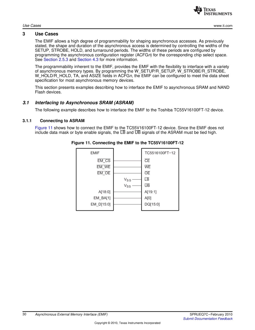
Figure 11 shows how to connect the EMIF to the TC55V16100FT-12 device. Since the EMIF does not include data mask or byte enable signals, the LB and UB signals of the ASRAM must be tied high.
Figure 11. Connecting the EMIF to the TC55V16100FT-12
EMIF
EM_CS
EM_WE
EM_OE
A[18:0] EM_BA[1] EM_D[15:0]
VS S
VS S
TC5516100FT−12
CE
WE
OE
LB
UB
A[19:1]
A[0]
DQ[15:0]
30 | Asynchronous External Memory Interface (EMIF) | SPRUEQ7C |
|
| Submit Documentation Feedback |
Copyright © 2010, Texas Instruments Incorporated