www.ti.com | Architecture |
1.3Functional Block Diagram
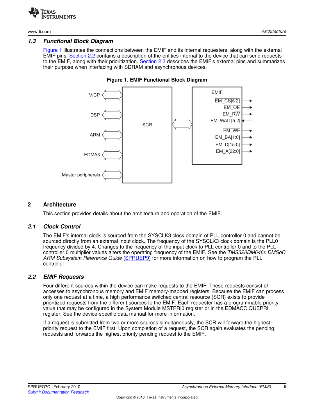
Figure 1 illustrates the connections between the EMIF and its internal requesters, along with the external EMIF pins. Section 2.2 contains a description of the entities internal to the device that can send requests to the EMIF, along with their prioritization. Section 2.3 describes the EMIF'sexternal pins and summarizes their purpose when interfacing with SDRAM and asynchronous devices.
Figure 1. EMIF Functional Block Diagram
VICP
DSP
ARM
EDMA3
SCR
EMIF
EM_CS[5:2] EM_OE EM_RW
EM_WAIT[5:2] ![]()
EM_WE ![]() EM_BA[1:0]
EM_BA[1:0] ![]() EM_D[15:0]
EM_D[15:0] ![]() EM_A[22:0]
EM_A[22:0] ![]()
Master peripherals
2Architecture
This section provides details about the architecture and operation of the EMIF.
2.1Clock Control
The EMIF'sinternal clock is sourced from the SYSCLK3 clock domain of PLL controller 0 and cannot be sourced directly from an external input clock. The frequency of the SYSCLK3 clock domain is the PLL0 frequency divided by 4. Changes to the frequency of the input clock to PLL controller 0 and to the PLL controller 0 multiplier values alters the operating frequency of the EMIF. See the TMS320DM646x DMSoC ARM Subsystem Reference Guide (SPRUEP9) for more information on how to program the PLL controller.
2.2EMIF Requests
Four different sources within the device can make requests to the EMIF. These requests consist of accesses to asynchronous memory and EMIF
If a request is submitted from two or more sources simultaneously, the SCR will forward the highest priority request to the EMIF first. Upon completion of a request, the SCR again evaluates the pending requests and forwards the highest priority pending request to the EMIF.
SPRUEQ7C | Asynchronous External Memory Interface (EMIF) | 9 |
Submit Documentation Feedback |
|
|
Copyright © 2010, Texas Instruments Incorporated
