www.ti.com | Registers |
4.9NAND Flash Status Register (NANDFSR)
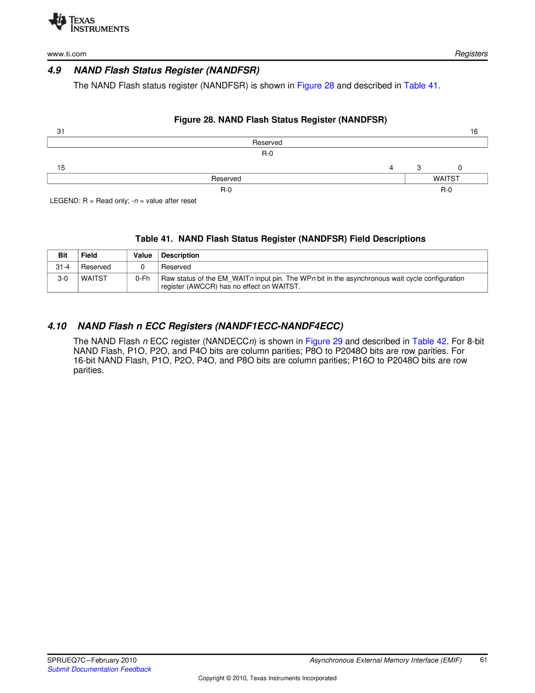
The NAND Flash status register (NANDFSR) is shown in Figure 28 and described in Table 41.
Figure 28. NAND Flash Status Register (NANDFSR)
31 |
|
| 16 |
| Reserved |
|
|
|
|
|
|
|
|
| |
15 | 4 | 3 | 0 |
|
|
|
|
Reserved |
|
| WAITST |
|
|
|
|
|
|
LEGEND: R = Read only;
Table 41. NAND Flash Status Register (NANDFSR) Field Descriptions
Bit | Field | Value | Description |
|
|
|
|
Reserved | 0 | Reserved | |
|
|
|
|
WAITST | Raw status of the EM_WAITn input pin. The WPn bit in the asynchronous wait cycle configuration | ||
|
|
| register (AWCCR) has no effect on WAITST. |
|
|
|
|
4.10NAND Flash n ECC Registers (NANDF1ECC-NANDF4ECC)
The NAND Flash n ECC register (NANDECCn) is shown in Figure 29 and described in Table 42. For
SPRUEQ7C | Asynchronous External Memory Interface (EMIF) | 61 |
Submit Documentation Feedback |
|
|
Copyright © 2010, Texas Instruments Incorporated