www.ti.com | Use Cases |
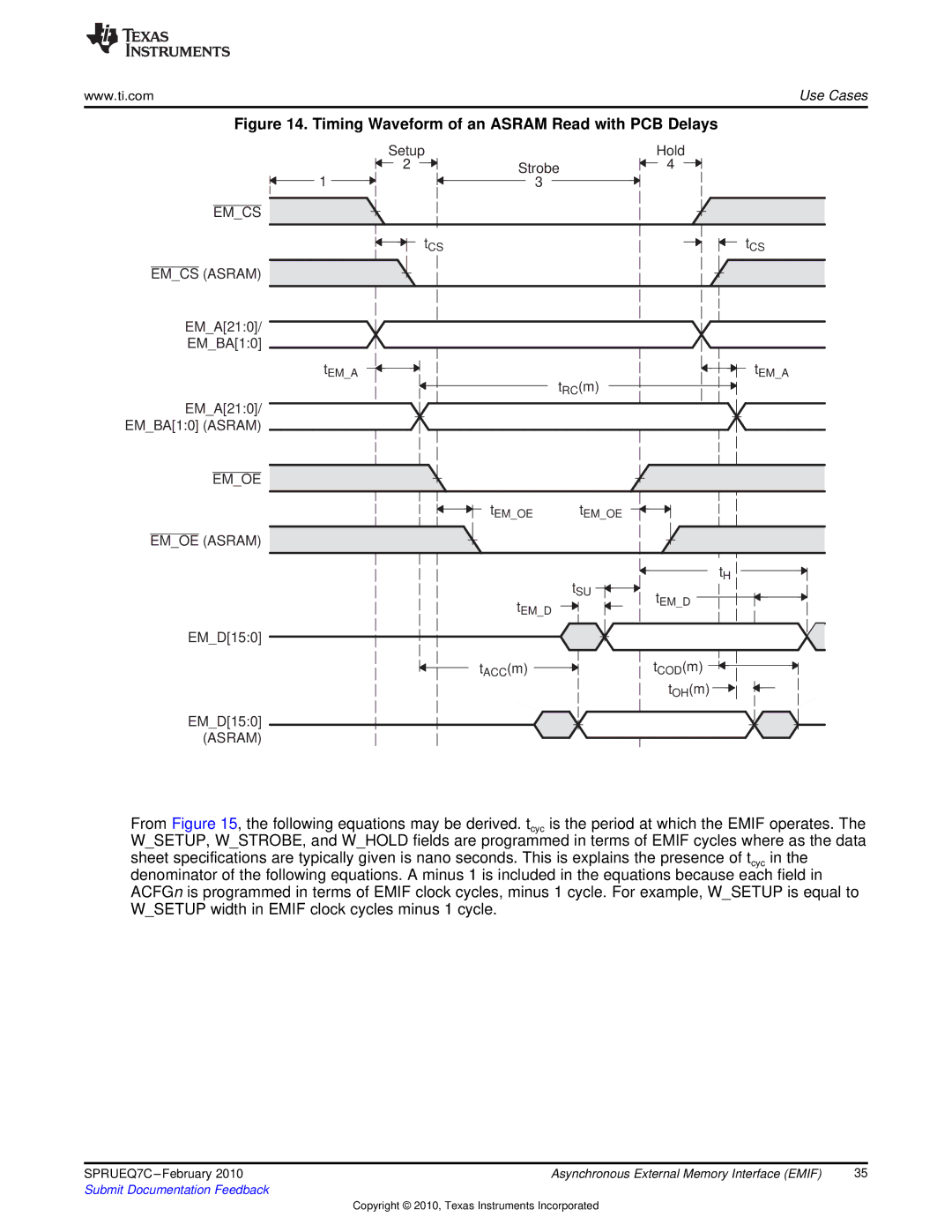
Figure 14. Timing Waveform of an ASRAM Read with PCB Delays
Setup ![]() 2
2 ![]()
1
Hold
Strobe![]() 4
4
3
EM_CS ![]()
![]()
tCS
EM_CS (ASRAM) ![]()
![]()
EM_A[21:0]/
EM_BA[1:0]
tCS
tEM_A
EM_A[21:0]/
EM_BA[1:0] (ASRAM)
tEM_A
tRC(m)
EM_OE ![]()
![]()
tEM_OE tEM_OE
EM_OE (ASRAM) ![]()
![]()
tSU
tEM_D
tH
tEM_D
EM_D[15:0]
tACC(m) ![]() tCOD(m)
tCOD(m) ![]() tOH(m)
tOH(m) ![]()
![]()
EM_D[15:0] (ASRAM)
From Figure 15, the following equations may be derived. tcyc is the period at which the EMIF operates. The W_SETUP, W_STROBE, and W_HOLD fields are programmed in terms of EMIF cycles where as the data sheet specifications are typically given is nano seconds. This is explains the presence of tcyc in the denominator of the following equations. A minus 1 is included in the equations because each field in ACFGn is programmed in terms of EMIF clock cycles, minus 1 cycle. For example, W_SETUP is equal to W_SETUP width in EMIF clock cycles minus 1 cycle.
SPRUEQ7C | Asynchronous External Memory Interface (EMIF) | 35 |
Submit Documentation Feedback |
|
|
Copyright © 2010, Texas Instruments Incorporated