4 Replacement Procedures
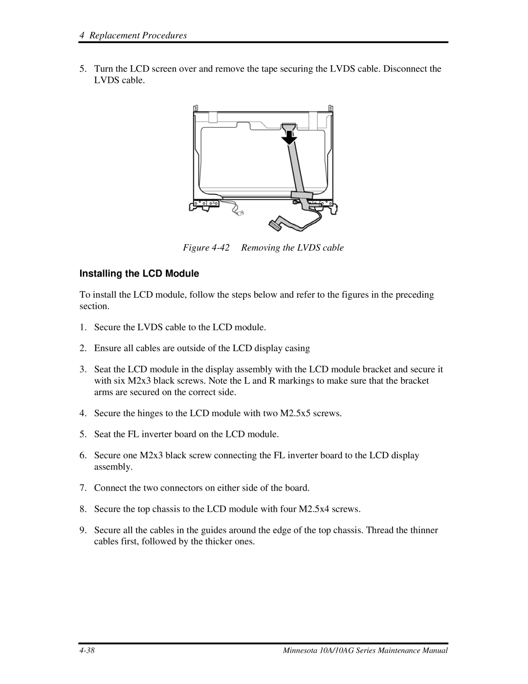
5.Turn the LCD screen over and remove the tape securing the LVDS cable. Disconnect the LVDS cable.
Figure 4-42 Removing the LVDS cable
Installing the LCD Module
To install the LCD module, follow the steps below and refer to the figures in the preceding section.
1.Secure the LVDS cable to the LCD module.
2.Ensure all cables are outside of the LCD display casing
3.Seat the LCD module in the display assembly with the LCD module bracket and secure it with six M2x3 black screws. Note the L and R markings to make sure that the bracket arms are secured on the correct side.
4.Secure the hinges to the LCD module with two M2.5x5 screws.
5.Seat the FL inverter board on the LCD module.
6.Secure one M2x3 black screw connecting the FL inverter board to the LCD display assembly.
7.Connect the two connectors on either side of the board.
8.Secure the top chassis to the LCD module with four M2.5x4 screws.
9.Secure all the cables in the guides around the edge of the top chassis. Thread the thinner cables first, followed by the thicker ones.
Minnesota 10A/10AG Series Maintenance Manual |