Manuals
/
Brands
/
Computer Equipment
/
Personal Computer
/
Toshiba
/
Computer Equipment
/
Personal Computer
Toshiba
a210
2.15 Camera Troubleshooting
1
69
253
253
Download
253 pages, 5.46 Mb
40
2 Troubleshooting Procedures
Satellite A210/ A215, Satellite Pro A210, EQUI
UM A210, SATEGO A210 Series Maintenance Manual
40
2.15 Camera
Troubleshooting
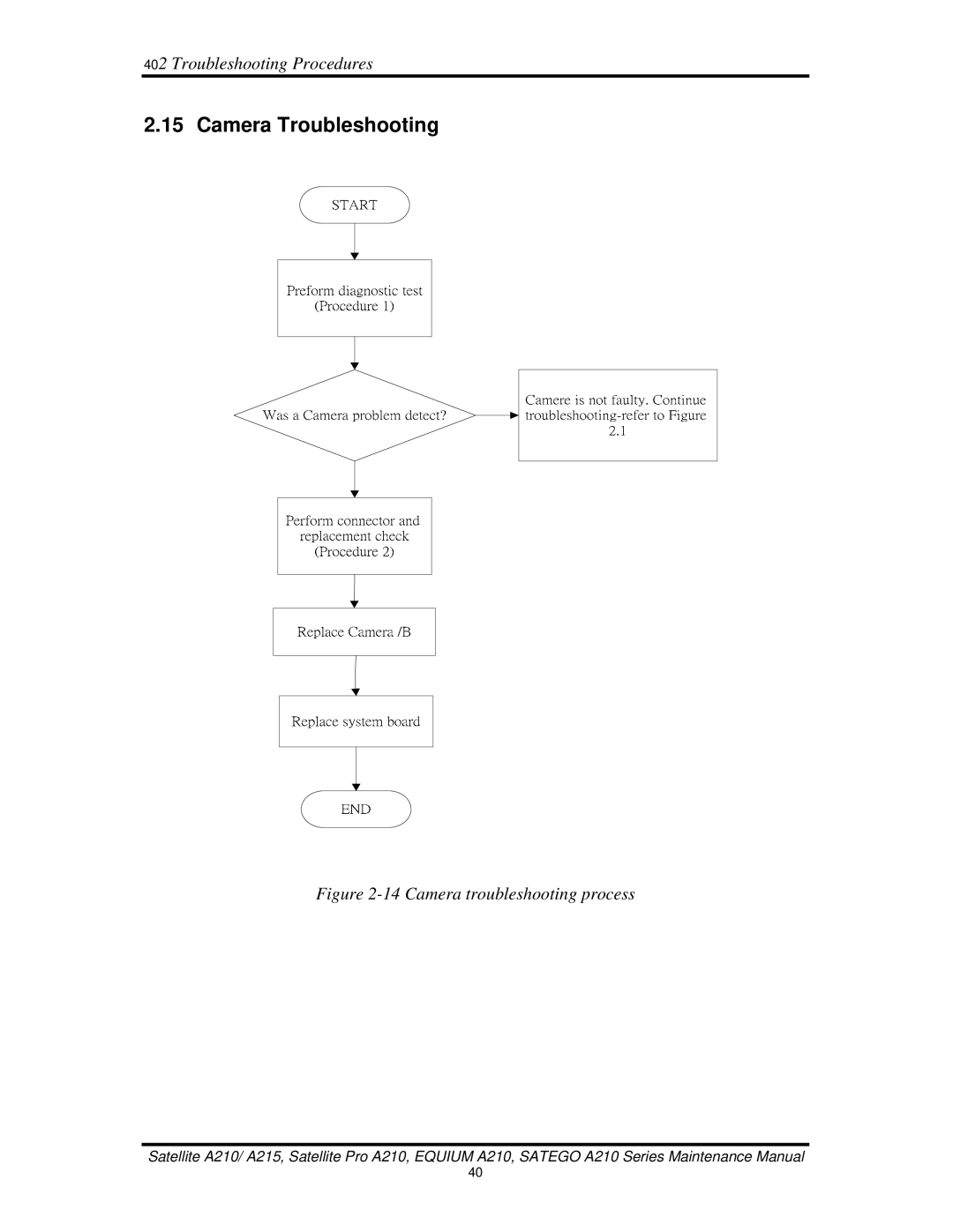
Figure 2-14 Camera troubleshooting process
Contents
Main
Toshiba Personal Computer Satellite A210 Maintenance Manual
TOSHIBA CORPORATION
Page
Preface
Page
Page
Table of Contents
Page
Page
Page
Page
Page
Chapter 1 Contents
Page
1.1 Features
Page
Page
Page
1.2 System Unit
1.3 2.5-inch Hard Disk Drive
Page
1.4 Optical Disc Device
Page
1.5 Power Supply
Page
1.6 Batteries
Page
Page
Chapter 2 Troubleshooting Procedures
Page
Chapter 2 Contents
Page
2.1 Troubleshooting Introduction
2.2 Troubleshooting Flowchart
2 Troubleshooting Procedures
A
Figure 2-1 Troubleshooting flowchart (1/2)
2 Troubleshooting Procedures
A
Figure 2-1 Troubleshooting flowchart (2/2)
Page
Page
2 Troubleshooting Procedures
2.3 Power Supply Troubleshooting
Figure 2-2 Power Supply Troubleshooting Process
END
Page
Page
Page
AC adaptor System board Batt ery
AC adaptor cord AC power cord
Page
2 Troubleshooting Procedures
2.4 Display Troubleshooting
Figure 2-3 Display troubleshooting process
Page
Page
2.5 Keyboard Troubleshooting
Page
2 Troubleshooting Procedures
2.6 External USB Devices Troubleshooting
Page
2 Troubleshooting Procedures
2.7 TV-Out Failure Troubleshooting
Figure 2-6 TV-out troubleshooting process
Page
2 Troubleshooting Procedures
2.8 TouchPad Troubleshooting
Figure 2-7 Touchpad troubleshooting process
Page
2 Troubleshooting Procedures
2.9 Speaker Troubleshooting
Figure 2-8 Speaker troubleshooting process
Page
2 Troubleshooting Procedures
2.10 Optical Drive Troubleshooting
Figure 2-9 Optical drive troubleshooting process
Page
Page
2.11 Modem Troubleshooting
Figure 2-10 Modem troubleshooting process
Page
2.12 Express card Troubleshooting
Figure 2-11 Express card troubleshooting process
Page
2.13 IEEE 1394 Troubleshooting
Figure 2-12 IEEE 1394 troubleshooting process
Page
2.14 Wireless LAN Troubleshooting
Procedure 1 Diagnostic test
Procedure 2 Connector and replacement check
Procedures
Page
2.15 Camera Troubleshooting
Page
2.16 Bluetooth Troubleshooting
Figure 2-15 Bluetooth troubleshooting process
Procedure 1 Diagnostic test
Procedure 2 Connector and replacement check
Procedures
2.17 4 in 1 card Troubleshooting
Procedure 1 4 in 1 card test
Procedure 2 4 in 1 Card socket replacement check
2.18 HDD Troubleshooting
Page
2.19 CRT Troubleshooting
Figure 2-18 HDD troubleshooting process
Procedure 1 CRT connection check
Procedure 2 CRT set check
502 Troubleshooting Procedures
50
2.20 HDMI Troubleshooting
Figure 2-19 HDMI troubleshooting process
Procedure 1 HDMI connection check
Procedure 2 HDMI set check
Page
Page
Page
Page
Page
Page
3.1 The Diagnostic Test
3.2 Executing the Diagnostic Test
Page
Page
Page
3.3 Display Configuration
3.4 Speaker Audio Test
3.5 Fan ON/OFF Test
3.6 Main Battery Charge Test
3. 7 FDD Test
3. 8 ODD Test
3. 9 Keyboard Test
3.10 Mouse (Pad) Test
Page
3. 11 LCD Pixels Mode Test
3.12 Magnetic Switch Test
Page
3.13 LAN Test
Page
Page
3.14 RTC Test
3.15 Read 1394 GUID
3.16 Speaker EQ Type Check&Re-Write
3.17 Button Test
Page
Page
Page
Page
3.19 Front Edge Logo
Notice: Check logo LED on/off function.
3.20 Fingerprint DOS Test
Page
3.21 Clear Fingerprint Test
Page
3.22 Write DMI
Page
Page
Page
Page
Chapter 4 Contents
Page
Page
Page
4.1 General
Page
Page
Page
Page
Page
4.2 Battery
Page
4.3 PC Card
Page
4.4 Memory Card
Page
4.5 HDD
Page
Page
4.6 Expansion Memory
Page
Page
4.7 Optical Drive Module
Page
4.8 Optical Drive
Page
4.9 Keyboard
Page
Page
4.10 Display Assembly
Page
Page
Page
Page
4.11 Display Mask
Page
Page
4.12 FL Inverter Board
Page
4.13 LCD Module
Page
Page
4.14 WLAN antennas
4.15 Camera and Microphone
Page
4.16 Bluetooth module
Page
4.17 Touch Pad
Page
4.18 Fingerprint Module
Page
4.19 Speakers
Page
4.20 Function Button Board
Page
4.21 USB Board
Page
4.22 MDC Card
Page
4.23 Wireless Module
4.24 System Fan
Page
4.25 System Board
Page
Page
4.26 VGA Board
Page
Page
4.27 CPU
Page
Page
Appendix A Handling the LCD Module
Precautions for handling the LCD module
Page
Page
Page
Page
Appendix B Board Layout
B.1 System Board Top View
B.2 System Board Bottom View
Page
Table B-2 System Board Connectors (top and bottom)
Page
Appendix C Pin Assignments
System Board C.1 JP31,JP33
Table C-1 SODIMM I/F pin assignments (200-PIN) (1/4)
Table C-1 SODIMM I/F pin assignments (200-PIN) (2/4)
Table C-1 SODIMM I/F pin assignments (200-PIN) (3/4)
C.2 JP24
C.3 JP34
Table C-3 HDD I/F pin assignments (22-pin)
C.4 JP29
Table C-4 ODD I/F pin assignments (52-pin)
C.5 JP5
Table C-5 Mini-Express (3G) I/F pin assignments (52-pin)
C.6 JP7
Table C-6 Mini-Express (WLAN) I/F pin assignments (52-pin)
C7 JP19
Table C-7 K/B connector pin assignments (34-pin)
C.8 JP8
Table C-8 Fan I/F pin assignments (3-pin)
C.9 JP14
Table C-9 MDC Connector pin assignments (12-pin)
C.10 PJP1
C.11 JP39
C.12 JP38
C.13 JP23
Table C-13 VGA/B Connector pin assignments (200-PIN) (1/4)
Table C-13 VGA/B Connector pin assignments (200-PIN) (2/4)
Table C-13 VGA/B Connector pin assignments (200-PIN) (3/4)
C.14 JP26
C.15 JP37
C.16 JP36
C.17 JP20
C.18 JP2
C.19 JP15
C.20 JP11
C.21 JP16
C.22 JP28
C.23 JP12
C.24 JP6
C.25 JP18
C.26 JP22
C.27 JP30
C.28 JP32
Appendix D Keyboard Scan/Character Codes
Table D-1 Scan codes (set 1 and set 2) (1/4)
Table D-1 Scan codes (set 1 and set 2) (2/4)
Table D-1 Scan codes (set 1 and set 2) (3/4)
Page
Page
Table D-3 Scan codes in Numlock mode
Table D-4 Scan codes with Fn keyiI
Table D-5 Scan codes in overlay mode
Table D-6 No.124 key scan code
Page
Page
Page
Page
Page
Page
Page
Page
Page
Page
Page
Page
Page
Page
Page
Page
Page
Appendix F Series Screw Torque List (IALAA)
Table F-1 Series Screw Torque List (High-end)
Page
Page
Appendix G Reliability