Series
CE Compliance for EU only
Vorsicht
Series
Waste Recycling information for users
Safety Summary
Meanings of Each Symbol
Precautions
Request Regarding Maintenance
Table of Contents
E5-1
E3-1
E4-1
EA1-1
Introduction Features
Product Overview
Unpacking
Accessories
Dimensions
Appearance
Front View Rear View
Operation Panel
Interior
Options
Option Name Type Description
Procedure
Printer Setup
Setup Flow
Manual threshold setting
Installation
Assembling the Accessories
Assembling the Supply Holder Frame
Connecting the Power Cord
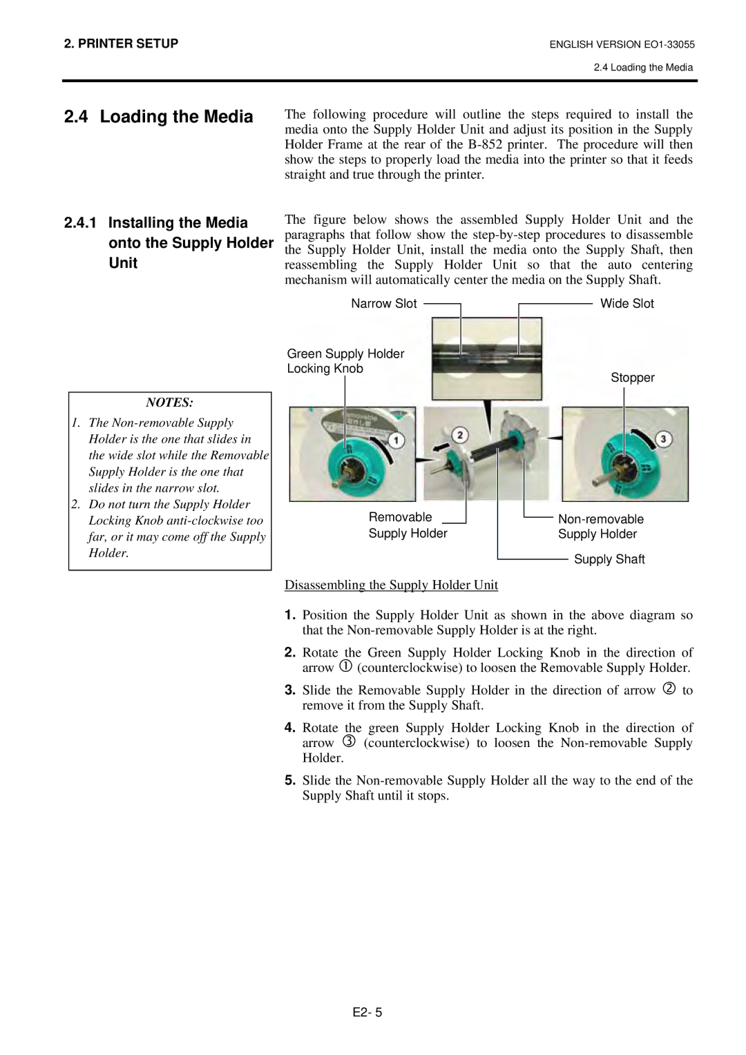
Straight and true through the printer
Installing the Media onto the Supply Holder Unit
Loading the Media
Disassembling the Supply Holder Unit
Spacer Supply Holder
Loading Media into the Printer
Print Head Element Head Block Release Lever
Down
Setting Sensor Positions
Setting the Feed Gap Sensor
Setting the Black Mark Sensor
Loading the Ribbon
Connecting the Cables to Your Printer
Turning the Printer
Turning on the Printer
How to enter the System Mode
Environment
Time the Pause key is pressed, the sub menus are displayed
Parameter Setting
While 2PARAMETER SET is displayed on the LCD Message
Sequentially
Use the Feed or Restart key to select a desired option
Character Zero Selection
Character Code Selection
After selecting a character code, press the Pause key
Data Length Selection
Baud Rate Selection
After selecting a baud rate, press the Pause key
After selecting a data length, press the Pause key
Stop Bit Length Selection
Parity Selection
Flow Control Code Selection
Auto Forward Wait Selection
LCD Language Selection
After selecting a language, press the Pause key
After selecting an auto forward wait, press the Pause key
Control Code Selection
Feed key
Feed Key Function Selection
After selecting the Feed key function, press the Pause key
Euro Code Selection
Kanji Code Selection
After selecting a Kanji code, press the Pause key
After selecting a Euro code, press the Pause key
Centronics Interface ACK/BUSY Timing Selection
Auto Print Head Check Selection
After selecting auto print head check, press the Pause key
After selecting an ACK/BUSY timing, press the Pause key
Web Printer Function Selection
Input Prime Selection
After selecting the Input Prime, press the Pause key
Expansion I/O Interface Type Selection
Plug & Play Selection
After selecting a Plug & Play, press the Pause key
Maxi Code Specification Selection
Label End/Ribbon End Selection
After selecting a Label End type, press the Pause key
Use the Feed or Restart key to select a printing method
Dump Mode Setting
After selecting the receive buffer, press the Pause key
After selecting a printing method, press the Pause key
Data in the receive buffer is printed as follows
Receive Buffer Size
Required Label Length
Basic Expansion Mode
When the Pause key is pressed, Basic program is executed
Not activated Activated Feed gap sensor Black mark sensor
LAN Setting
Date Setting
Time Setting
Real Time Clock Setting 3 Low Battery Check Setting
RTC Data Renewal Timing Setting
Cont
IP Address Setting TCP/IP
Feed and Pause keys
Gateway IP Address
Printer IP Address
This parameter is to set an IP address
This parameter is to set a Gateway IP address
Subnet Mask
This parameter is to set a Subnet Mask
Socket Port
Dhcp Client ID
This parameter is to enable Dhcp
Dhcp
This parameter is to set a Dhcp client ID
Dhcp Host Name
This parameter is to set a Dhcp host name
Ascii code and Hex. code correspondence table
Installing the Printer Drivers
Introduction
General Description
Installing the Printer Driver
Parallel Interface
Windows 98/Me
E2-43
Windows 2000/XP
E2-45
USB Interface
E2-47
E2-48
E2-49
Finish button
E2-51
E2-52
E2-53
Uninstalling the Printer Driver
Adding/Deleting a LAN Port
Adding a LAN Port Windows 98/ME
Deleting a LAN Port
Printer Driver Upgrades
Others
Using the Printer Driver
Adjustment
Print Test
When using an optional Cutter Module
Coordinate Fine Adjustment
Position and Print Tone Fine Adjustment
Feed Amount Fine Adjustment
Threshold Fine Adjustment Feed gap sensor
After selecting a fine adjustment value, press the Pause key
When setting +0.0 mm
Position and Print Tone Fine Adjustment
Restart Feed
When setting -50.0 mm
When setting +50.0 mm
Print Tone Fine Adjustment
Ribbon Motor Voltage Fine Adjustment
Select the sensor to be adjusted by using the Feed key
Threshold Setting
Jam errors
Manually set
Feed Gap Sensor Adjustment
Upper Black Mark Sensor Adjustment
Lower Black Mark Sensor Adjustment
Lower Black Mark Sensor/Feed Gap Sensor Adjustment No media
„ When using the Black Mark Sensor
„ When using the Feed Gap Sensor
„ Manual Threshold Setting
„ Storing a No Media Level Voltage
Press and hold the Restart or Feed key for about 3 seconds
Feed Gap Sensor
Used to stop printing temporarily
On Line Mode
Operation Panel
Used to restart printing
Operation Reset
Press and hold the Restart key for 3 seconds or longer
Maintenance
Cleaning
Print Head/Platen/ Sensors
Covers and Panels
Optional Cutter Module
Error Messages Problems/Causes
Troubleshooting
Error Messages
Solutions
Error Messages Problems/Cause
Media has run out
Restart key
Possible Problems
Possible Problems Causes
Clean the Cutter Blade
Load the ribbon properly
Attach the Cutter Cover properly Remove the jammed paper
Removing Jammed Media
Printer Specifications
This section describes the printer specifications
Model 852-TS22-QQ-R 852-TS22-QP-R
Mail 4STATE Customer CODE, RSS14
Media Type
Supply Specifications
Media
Label
Detection Area of the Transmissive Sensor
Detection Area of the Reflective Sensor
Effective Print Area
Figure below shows the effective print area on the media
Ribbon
Recommended Media and Ribbon Types
Media type Description
Combination of Media and Ribbon
Care/Handling of the Media and Ribbon
Ribbon type Description
Media type Vellum paper and label
Symbols in the message
Appendix 1 Messages and Leds
100BASE LAN is being initialised
Command error has occurred
Analyzing the command
Dhcp Client is being initialised
Following message appears
Appendix 2 Interface
Parallel interface Centronics
Connector
Standard
Number of ports Power source Self power Connector Type B
Number of ports Connector RJ-45
LED status Link LED
Serial interface Option B-SA704-RS-QM-R
Wireless LAN Option B-SA704-WLAN-QM-R
Expansion I/O Interface Option B-SA704-IO-QM-R
Appendix 3 Print Samples
CODE39 Full Ascii
JAN8, EAN8 MSI Interleaved 2
NW7 JAN13, EAN13 UPC-E EAN13+2 digits EAN13+5 digits
UPC-E+2 digits UPC-E+5 digits EAN8+2 digits EAN8+5 digits
Industrial 2 Data Matrix
UPC-A+2 digits
UPC-A+5 digits
Customer bar code of high priority QR code
Appendix 4 Glossaries
See Feed gap sensor
See Black mark sensor
Media and ribbon
USB Universal Serial Bus
Index
3-1, A1-1
Index
EO1-33055D