3.4OPERATING PROCEDURES
For Parallel Operation system, refer to section “D) MMS
A)
Before the UPS startup, the internal Bypass line starts to supply the unconditioned bypass input power to the load if the External input (or Bypass) Circuit Breaker is closed. Be
!extremely careful with closing the External input (or Bypass) Circuit Breaker.
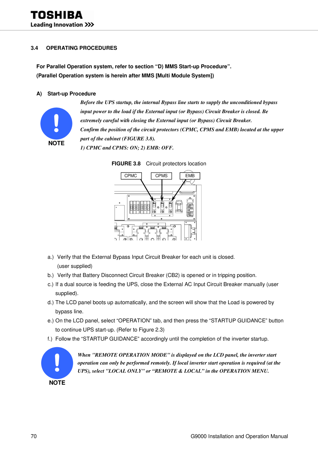
Confirm the position of the circuit protectors (CPMC, CPMS and EMB) located at the upper
NOTE
part of the cabinet (FIGURE 3.8).
1) CPMC and CPMS: ON; 2) EMB: OFF.
FIGURE 3.8 Circuit protectors location
CPMC
CPMS
EMB
a.) Verify that the External Bypass Input Circuit Breaker for each unit is closed. (user supplied)
b.) Verify that Battery Disconnect Circuit Breaker (CB2) is opened or in tripping position.
c.) If a dual source is feeding the UPS, close the External AC Input Circuit Breaker manually (user supplied).
d.) The LCD panel boots up automatically, and the screen will show that the Load is powered by bypass line.
e.) On the LCD panel, select “OPERATION” tab, and then press the “STARTUP GUIDANCE” button to continue UPS
f.) Follow the “STARTUP GUIDANCE” accordingly until the completion of the inverter startup.
!operation can only be performed remotely. If local inverter start operation is required (at the UPS), select "LOCAL ONLY" or “REMOTE & LOCAL” in the OPERATION MENU.When "REMOTE OPERATION MODE" is displayed on the LCD panel, the inverter start
NOTE
70 | G9000 Installation and Operation Manual |
