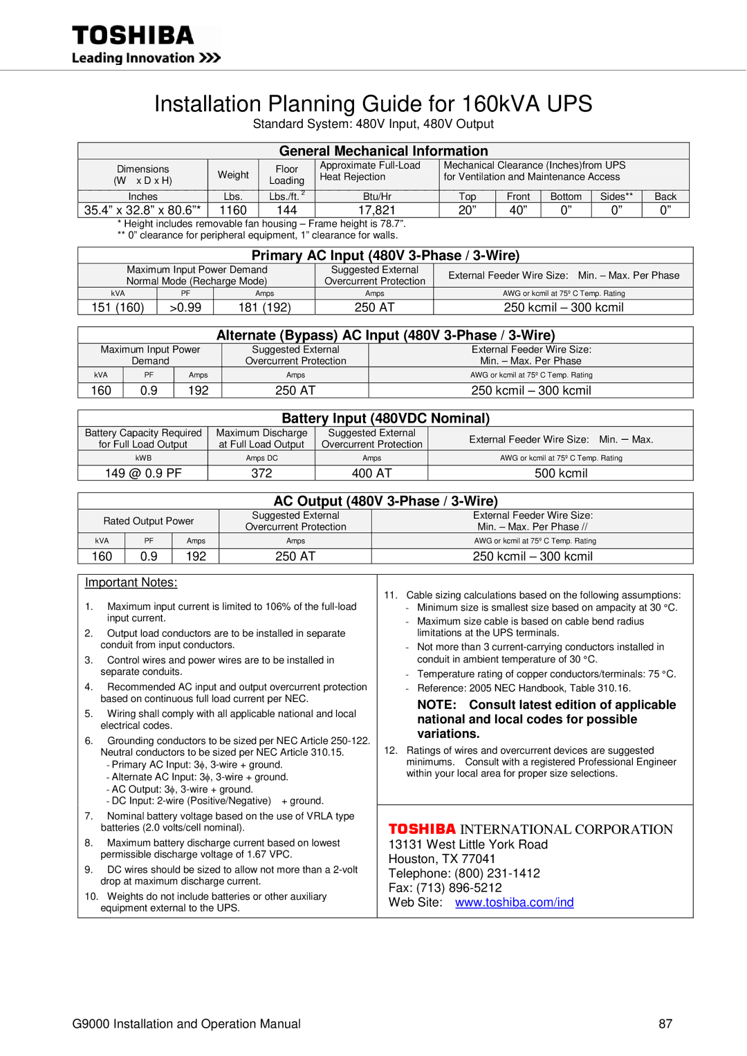
Installation Planning Guide for 160kVA UPS
Standard System: 480V Input, 480V Output
General Mechanical Information
Dimensions | Weight | Floor |
| Approximate |
| Mechanical Clearance (Inches)from UPS |
| |||
| Heat Rejection |
| for Ventilation and Maintenance Access |
| ||||||
(W x D x H) | Loading |
|
|
| ||||||
|
|
|
|
|
|
|
|
| ||
Inches | Lbs. | Lbs./ft. 2 |
| Btu/Hr |
| Top | Front | Bottom | Sides** | Back |
35.4” x 32.8” x 80.6”* | 1160 | 144 | 17,821 |
| 20” | 40” | 0” | 0” | 0” | |
*Height includes removable fan housing – Frame height is 78.7”.
**0” clearance for peripheral equipment, 1” clearance for walls.
Primary AC Input (480V 3-Phase / 3-Wire)
| Maximum Input Power Demand |
|
| Suggested External |
| External Feeder Wire Size: Min. – Max. Per Phase | ||
| Normal Mode (Recharge Mode) |
|
| Overcurrent Protection |
| |||
|
|
|
|
| ||||
| kVA | PF | Amps |
|
| Amps |
| AWG or kcmil at 75º C Temp. Rating |
| 151 (160) | >0.99 | 181 (192) |
|
| 250 AT |
| 250 kcmil – 300 kcmil |
Alternate (Bypass) AC Input (480V 3-Phase / 3-Wire)
Maximum Input Power | Suggested External | External Feeder Wire Size: | ||
| Demand |
| Overcurrent Protection | Min. – Max. Per Phase |
kVA | PF | Amps | Amps | AWG or kcmil at 75º C Temp. Rating |
160 | 0.9 | 192 | 250 AT | 250 kcmil – 300 kcmil |
Battery Input (480VDC Nominal)
| Battery Capacity Required |
|
| Maximum Discharge |
|
| Suggested External |
| External Feeder Wire Size: Min. – Max. |
| for Full Load Output |
|
| at Full Load Output |
|
| Overcurrent Protection |
| |
| kWB |
|
| Amps DC |
|
| Amps |
| AWG or kcmil at 75º C Temp. Rating |
| 149 @ 0.9 PF |
| 372 |
|
| 400 AT |
| 500 kcmil | |
AC Output (480V 3-Phase / 3-Wire)
|
| Rated Output Power |
| Suggested External |
|
|
| External Feeder Wire Size: |
|
| ||||
|
|
| Overcurrent Protection |
|
|
| Min. – Max. Per Phase // |
|
| |||||
|
|
|
|
|
|
|
|
|
|
|
| |||
|
| kVA | PF |
| Amps |
|
| Amps |
|
| AWG or kcmil at 75º C Temp. Rating |
|
| |
| 160 | 0.9 |
| 192 |
|
| 250 AT |
|
| 250 kcmil – 300 kcmil |
|
| ||
|
|
|
|
|
|
|
|
|
|
|
| |||
| Important Notes: |
|
|
|
|
|
| 11. Cable sizing calculations based on the following assumptions: |
|
| ||||
| 1. | Maximum input current is limited to 106% of the |
|
|
| |||||||||
|
| - Minimum size is smallest size based on ampacity at 30 °C. |
|
| ||||||||||
|
| input current. |
|
|
|
|
|
| - Maximum size cable is based on cable bend radius |
|
| |||
| 2. | Output load conductors are to be installed in separate |
| limitations at the UPS terminals. |
|
| ||||||||
|
| conduit from input conductors. |
|
|
|
| - Not more than 3 |
|
| |||||
| 3. | Control wires and power wires are to be installed in |
| conduit in ambient temperature of 30 °C. |
|
| ||||||||
|
| separate conduits. |
|
|
|
|
|
| - Temperature rating of copper conductors/terminals: 75 °C. |
|
| |||
| 4. | Recommended AC input and output overcurrent protection |
| - Reference: 2005 NEC Handbook, Table 310.16. |
|
| ||||||||
|
| based on continuous full load current per NEC. |
| NOTE: | Consult latest edition of applicable |
|
| |||||||
| 5. | Wiring shall comply with all applicable national and local |
|
|
| |||||||||
|
| national and local codes for possible |
|
| ||||||||||
|
| electrical codes. |
|
|
|
|
|
|
|
| ||||
|
|
|
|
|
|
|
| variations. |
|
| ||||
| 6. | Grounding conductors to be sized per NEC Article |
|
|
| |||||||||
|
| 12. Ratings of wires and overcurrent devices are suggested |
|
| ||||||||||
|
| Neutral conductors to be sized per NEC Article 310.15. |
|
|
| |||||||||
|
|
|
|
| φ |
|
|
|
| minimums. | Consult with a registered Professional Engineer |
|
| |
|
| - Primary AC Input: 3 , |
| within your local area for proper size selections. |
|
| ||||||||
|
| - Alternate AC Input: 3φ, |
|
|
| |||||||||
|
| - AC Output: 3φ, |
|
|
|
|
|
|
| |||||
|
| - DC Input: | + ground. |
|
|
|
|
| ||||||
| 7. | Nominal battery voltage based on the use of VRLA type |
| TOSHIBA INTERNATIONAL CORPORATION |
|
| ||||||||
|
| batteries (2.0 volts/cell nominal). |
|
|
|
|
|
| ||||||
| 8. | Maximum battery discharge current based on lowest |
| 13131 West Little York Road |
|
| ||||||||
|
| permissible discharge voltage of 1.67 VPC. |
| Houston, TX 77041 |
|
| ||||||||
| 9. | DC wires should be sized to allow not more than a |
| Telephone: (800) |
|
| ||||||||
|
| drop at maximum discharge current. |
|
|
| Fax: (713) |
|
| ||||||
| 10. Weights do not include batteries or other auxiliary |
|
|
| ||||||||||
|
| Web Site: www.toshiba.com/ind |
|
| ||||||||||
|
| equipment external to the UPS. |
|
|
|
|
|
| ||||||
|
|
|
|
|
|
|
|
|
| |||||
|
|
|
|
|
|
|
|
|
|
|
|
|
|
|
G9000 Installation and Operation Manual | 87 |