Document 4GBA0012 Rev. E January
Page
Document No GBA0012 Rev. E January
Page
Uninterruptible Power System
Important Notice
Purpose and Scope of Manual
Table of Contents
List of Tables
List of Figures
Power wire connections parallel system configuration
How to use this Manual
Important Safety Instructions
Safety Precautions
UPS Installation Environment
Environment standard
Capacity kVA Bypass Voltage Vac Bypass Rating Aac Breaker a
General
Definitions
Operation Overview
CB3 Mccb
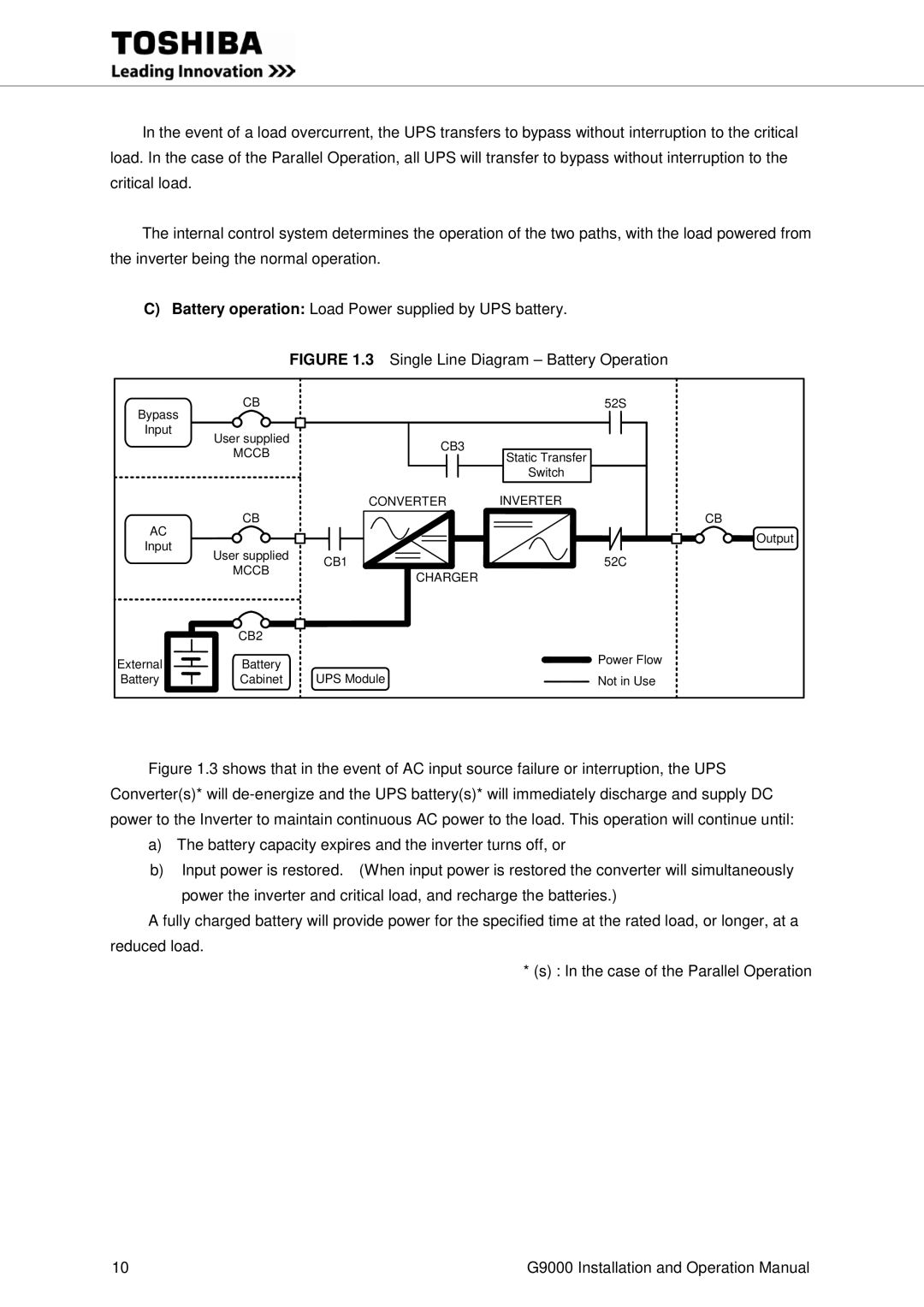
Single Line Diagram Battery Operation
Page
1 UPS Parts Location 80,100kVA
UPS cabinet Front Inside View
UPS cabinet Front View
UPS Parts Location 300kVA Door Backside Main Cabinet
4 UPS Parts Location 500kVA UPS cabinet Front View
Backside of Left Door
Item 10 Grounding bar is not shown in .4.5. Refer to Figure
Reset switch Button Test switch
12. SW5 13. SW6
1 Parallel I/F PCB IFAU-08 80-225kVA
CN96 CN95 CN94
LCD Touch Panel Monitor Display
External I/F PCB IOAU-09 Figure Signal I/F on IOAU-09 board
Description of Figures 1.4.1-5 to
15 L S/W switch for Service Personnel only
External contact signal terminal block
Refer to Figures 3.7.1 to 3.7.4 for details
AC input, AC output, DC input terminal
Specifications
80kVA / 72kW 480V
Width Depth Height Net Weight Typical
Width Depth Height Gross Weight Lbs KVA
UPS
Lbs Heating KVA Knockout KBTU/h
A Detail of Specifications
AC Input
Operating Temperature
Cooling
Phase I 80-225kVA Phase II 300-750kVA
Rating of Contactors, Breakers and Fuses
Output Capacity of Equipment Number Application
Operator Controls and Indicators
Battery operation Battery OP. orange
EPO Button Emergency Power Off button
LED Display
Load on inverter Load on Inverter green
Startup/Shutdown Guidance Figures 2.3.1 to
Liquid Crystal Display
Menu
2 Startup guidance
2 Output values
1 Log menu
Input Power Failure
Fault Indication
Message
External Signal Terminal Block
Summary Alarm Triggers on fault alarm only
OUT8 Total Alarm Triggers on any alarm including faults
TN2
Battery Breaker Panel
TN1
Output Contacts for external alarm annunciation
Terminals 7 to 8 Battery Operation contact OUT3
Terminals 11 to 12 Battery Low Voltage contact OUT5
Terminals 3 to 4 Load on Bypass contact OUT1
Input Contacts for remote access of UPS
12 Remote Start Contact Connections
Terminals 11 to 12 Battery Temp. High contact input IN3
Terminals 13 to 14 Power Demand Command contact input IN4
Used to perform a remote UPS Emergency Power Off EPO
Terminals 9 to 10 Remote Inverter Stop input terminal IN2
13.1 Configuration of the RemotEyeII Overview 80-225kVA
RemotEyeII Introduction
Back of the front door Main cabinet RemotEyeII
DPAU-81
SW1 Cable2 Cable3 Provided
PSAU-60
SW1
Back of the front left door Main cabinet
Provided PSAU-60 PS1 Cable1
Male Cable3 12V Power Cable Cable2 Sub 9-pin Cable
Cable1 3BBA0083P001
15 PSAU-60 PCB PS1
Connector Definition Figure
Transportation and Installation
Transportation Installation
Installation Procedure
Space requirement for routine maintenance
External Battery Supply
Procedure for Cable Connections
UPS Capacity DC Voltage
KVA Rating Current Permitted a
Required
Page
Recommended Cable Sizes
Crimp Type Compression Lug
UPS Terminal Designation
Input A40,B40,C40
Location of bus bars and terminal blocks Bottom Entry
UPS module
Detailed Power Terminals
UPS module 300kVA
A50, B50, C50 Grounding Bar not shown 18.5
UPS module 500kVA
AC Output 78.7 A50, B50, C50 Grounding Bar Not shown 19.7
UPS module 750kVA
BUS BAR Detail
TOP View
BUS BAR Detail TOP View
BUS BAR Connection TOP View Alternate
Landing Main Cabinet
BUS BAR Connection
DC Breaker for Battery
Breaker 52Ln *1 AC output
CB2 Battery
Bypass52S Converter CB1 /Charger Inverter 52C
UPS-1
UPS-1
~~~~~
UPS-1
No.N UPS
Use Ethernet STP Shielded Twisted Pair Cable Cat 5 or
~~~~~
Operating Procedures
Circuit protectors location
Shut-down Procedure
Operation Menu
Bypass Operation Procedure
UPS
MMS Start-up Procedure
LCD Screen MMS Operation
Response to UPS Failure
UPS Component Parts
Battery
Replace battery if its capacity is within this percentage
Fault Codes
Failure Code List Fault Code
CB2 Open
DC Unbalanced
Overvoltage Engineer
Inverter Call Service
52S Abnormal
How to perform daily inspection
Daily Inspection
Page
Variations
Consult latest edition of applicable
National and local codes for possible
27.6 x 32.8 x 855 136 13,463
114 150 AT 3/0
100 120 150 AT 3/0
94 @ 0.9 PF 235 250 AT Kcmil 300 kcmil
35.4 x 32.8 x 1160 144 17,821
151 181 250 AT Kcmil 300 kcmil
160 192 250 AT Kcmil 300 kcmil
149 @ 0.9 PF 372 400 AT Kcmil
35.4 x 32.8 x 1230 152 25,060
212 255 350 AT Kcmil 2 x 250 kcmil
225 271 350 AT Kcmil 2 x 250 kcmil
210 @ 0.9 PF 524 600 AT 300 kcmil 2 x 400 kcmil
51.2 x 32.7 x 1230 189 31,659
312 376 500 AT 250 kcmil 2 x 300 kcmil
300 361 500 AT 4/0 2 x 250 kcmil
309 @ 1.0 PF 772 800 AT 400 kcmil
70.9 x 32.7 x 3300 205 52.8 23.6 42.3
521 626 800 AT 300 kcmil 3 x 350 kcmil
500 601 800 AT 300 kcmil 3 x 350 kcmil
512 @ 1.0 PF 1292 1400 AT 400 kcmil 4 x 500 kcmil
90.6 x 32.7 x 4255 207 79,147
781 939 1400 a 500 kcmil
750 902 1200 a X350 kcmil 4 x 400 kcmil
776 @ 1.0 PF 1935 2000 AT 400 kcmil 6 x 500 kcmil
Page
Page
Industrial Division