360014937
10.3.4 Series resistance
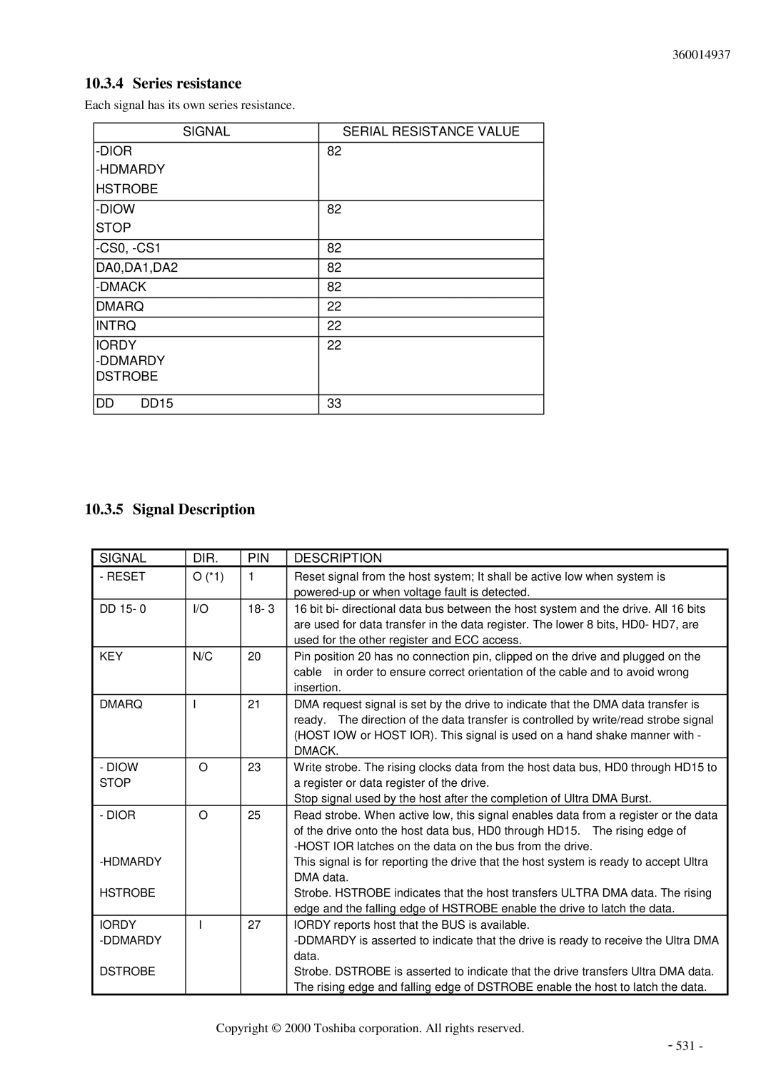
Each signal has its own series resistance.
SIGNAL | SERIAL RESISTANCE VALUE |
82Ω | |
| |
HSTROBE |
|
|
|
82Ω | |
STOP |
|
|
|
82Ω | |
DA0,DA1,DA2 | 82Ω |
82Ω | |
DMARQ | 22Ω |
INTRQ | 22Ω |
IORDY | 22Ω |
| |
DSTROBE |
|
|
|
DD0~DD15 | 33Ω |
10.3.5 Signal Description
SIGNAL | DIR. | PIN | DESCRIPTION |
- RESET | O (*1) | 1 | Reset signal from the host system; It shall be active low when system is |
|
|
| |
DD 15- 0 | I/O | 18- 3 | 16 bit bi- directional data bus between the host system and the drive. All 16 bits |
|
|
| are used for data transfer in the data register. The lower 8 bits, HD0- HD7, are |
|
|
| used for the other register and ECC access. |
KEY | N/C | 20 | Pin position 20 has no connection pin, clipped on the drive and plugged on the |
|
|
| cable in order to ensure correct orientation of the cable and to avoid wrong |
|
|
| insertion. |
DMARQ | I | 21 | DMA request signal is set by the drive to indicate that the DMA data transfer is |
|
|
| ready. The direction of the data transfer is controlled by write/read strobe signal |
|
|
| (HOST IOW or HOST IOR). This signal is used on a hand shake manner with - |
|
|
| DMACK. |
- DIOW | O | 23 | Write strobe. The rising clocks data from the host data bus, HD0 through HD15 to |
STOP |
|
| a register or data register of the drive. |
|
|
| Stop signal used by the host after the completion of Ultra DMA Burst. |
- DIOR | O | 25 | Read strobe. When active low, this signal enables data from a register or the data |
|
|
| of the drive onto the host data bus, HD0 through HD15. The rising edge of |
|
|
| |
|
|
| This signal is for reporting the drive that the host system is ready to accept Ultra |
|
|
| DMA data. |
HSTROBE |
|
| Strobe. HSTROBE indicates that the host transfers ULTRA DMA data. The rising |
|
|
| edge and the falling edge of HSTROBE enable the drive to latch the data. |
IORDY | I | 27 | IORDY reports host that the BUS is available. |
|
| ||
|
|
| data. |
DSTROBE |
|
| Strobe. DSTROBE is asserted to indicate that the drive transfers Ultra DMA data. |
|
|
| The rising edge and falling edge of DSTROBE enable the host to latch the data. |
Copyright © 2000 Toshiba corporation. All rights reserved.
- 531 -