360014937
10.3.2 Pin Assignment
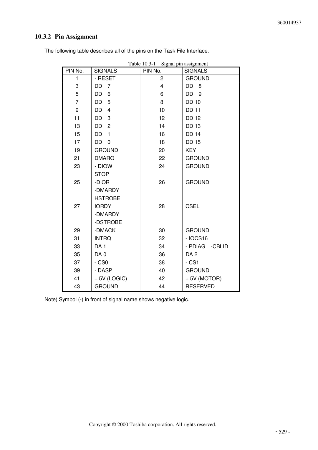
The following table describes all of the pins on the Task File Interface.
Table
PIN No. | SIGNALS | PIN No. | SIGNALS | ||
1 | - RESET | 2 | GROUND | ||
3 | DD | 7 | 4 | DD | 8 |
5 | DD | 6 | 6 | DD | 9 |
7 | DD | 5 | 8 | DD 10 | |
9 | DD | 4 | 10 | DD 11 | |
11 | DD | 3 | 12 | DD 12 | |
13 | DD | 2 | 14 | DD 13 | |
15 | DD | 1 | 16 | DD 14 | |
17 | DD | 0 | 18 | DD 15 | |
19 | GROUND | 20 | KEY |
| |
21 | DMARQ | 22 | GROUND | ||
23 | - DIOW | 24 | GROUND | ||
| STOP |
|
|
| |
25 | 26 | GROUND | |||
|
|
|
| ||
| HSTROBE |
|
|
| |
27 | IORDY | 28 | CSEL | ||
|
|
|
| ||
|
|
|
| ||
29 | 30 | GROUND | |||
31 | INTRQ | 32 | - IOCS16 | ||
33 | DA 1 |
| 34 | - | |
35 | DA 0 |
| 36 | DA 2 |
|
37 | - CS0 | 38 | - CS1 | ||
39 | - DASP | 40 | GROUND | ||
41 | + 5V (LOGIC) | 42 | + 5V (MOTOR) | ||
43 | GROUND | 44 | RESERVED | ||
|
|
|
|
|
|
Note) Symbol
Copyright © 2000 Toshiba corporation. All rights reserved.
- 529 -