360014937
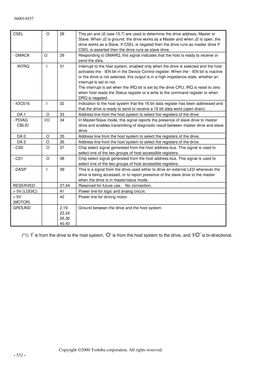
CSEL | O | 28 | This pin and J2 (see 10.7) are used to determine the drive address, Master or |
|
|
| Slave. When J2 is ground, the drive works as a Master and when J2 is open, the |
|
|
| drive works as a Slave. If CSEL is negated then the drive runs as master drive If |
|
|
| CSEL is asserted then the drive runs as slave drive. |
- DMACK | O | 29 | Responding to DMARQ, this signal indicates that the host is ready to receive or |
|
|
| send the data. |
INTRQ | I | 31 | Interrupt to the host system, enabled only when the drive is selected and the host |
|
|
| activates the - IEN bit in the Device Control register. When the - IEN bit is inactive |
|
|
| or the drive is not selected, this output is in a high impedance state, whether an |
|
|
| interrupt is set or not. |
|
|
| The interrupt is set when the IRQ bit is set by the drive CPU. IRQ is reset to zero |
|
|
| when host reads the Status register or a write to the command register or when |
|
|
| DRQ is negated. |
- IOCS16 | I | 32 | Indication to the host system that the 16 bit data register has been addressed and |
|
|
| that the drive is ready to send or receive a 16 bit data word (open drain). |
DA 1 | O | 33 | Address line from the host system to select the registers of the drive. |
- PDIAG | I/O | 34 | In Master/Slave mode, this signal reports the presence of slave drive to master |
/CBLID |
|
| drive and enables transmitting of diagnostic result between master drive and slave |
|
|
| drive |
DA 0 | O | 35 | Address line from the host system to select the registers of the drive. |
DA 2 | O | 36 | Address line from the host system to select the registers of the drive. |
- CS0 | O | 37 | Chip select signal generated from the host address bus. This signal is used to |
|
|
| select one of the two groups of host accessible registers. |
- CS1 | O | 38 | Chip select signal generated from the host address bus. This signal is used to |
|
|
| select one of the two groups of host accessible registers. |
- DASP | I | 39 | This is a signal from the drive used either to drive an external LED whenever the |
|
|
| drive is being accessed, or to report presence of the slave drive to the master |
|
|
| when the drive is in master/slave mode. |
RESERVED |
| 27,44 | Reserved for future use. No connection. |
+ 5V (LOGIC) |
| 41 | Power line for logic and analog circuit. |
+ 5V |
| 42 | Power line for driving motor. |
(MOTOR) |
|
|
|
GROUND |
| 2,19 | Ground between the drive and the host system. |
|
| 22,24 |
|
|
| 26,30 |
|
|
| 40,43 |
|
(*1) ‘I’ is from the drive to the host system, ‘O’ is from the host system to the drive, and ‘I/O’ is