8-5-1. Refrigerant Piping Connection
<Flaring>
(1) Cut the pipe with a pipe cutter.
90˚ | Obliquity Roughness | Warp |
Fig.
(2) Insert a flare nut into the pipe, and flare the pipe.
|
| A | Outer | A (mm) |
|
|
| ||
|
| diam. | Imperial Rigid | |
|
|
| ||
|
|
|
| |
|
|
| 6.35 mm 1.3 mm 0.7 mm | |
Die | Pipe |
| 9.52 mm 1.6 mm 1.0 mm | |
Fig.
<Tightening connection>
Align the centers of the connecting pipes and tighten the flare nut as far as possible with your fingers. Then tighten the nut with a spanner and torque wrench as shown in the figure.
CAUTION
•Do not apply excess torque. Otherwise, the nut may crack depending on the installation conditions.
(Unit : N·m)
Outer diam. | Tightening torque | Additional | |
tightening torque | |||
|
| ||
|
|
| |
6.35 mm | 15.7 (1.6 kgf·m) | 19.6 (2.0 kgf·m) | |
|
|
| |
9.52 mm | 29.4 (3.0 kgf·m) | 34.3 (3.5 kgf·m) |
8-5-2. Vacuum Pumping
AIR PURGE
Evacuate the air in the connecting pipes and in the indoor unit using vacuum pump.
Do not use the refrigerant in the outdoor unit.
For details, see the manual of vacuum pump.
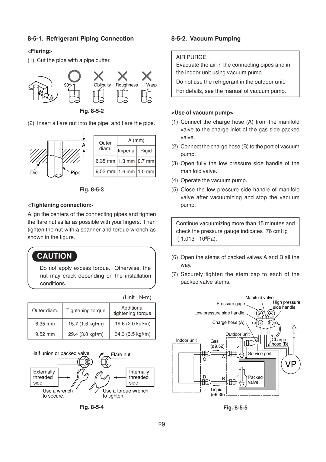
<Use of vacuum pump>
(1)Connect the charge hose (A) from the manifold valve to the charge inlet of the gas side packed valve.
(2)Connect the charge hose (B) to the port of vacuum pump.
(3)Open fully the low pressure side handle of the manifold valve.
(4)Operate the vacuum pump.
(5)Close the low pressure side handle of manifold valve after vacuumizing and stop the vacuum pump.
Continue vacuumizing more than 15 minutes and check the pressure gauge indicates
(6)Open the stems of packed valves A and B all the way.
(7)Securely tighten the stem cap to each of the packed valve stems.
| Manifold valve | |
Pressure gage | High pressure | |
side handle | ||
| ||
Low pressure side handle |
| |
Charge hose (A) | Lo Hi | |
Outdoor unit | ||
Half union or packed valve | Flare nut |
Externally | Internally |
threaded | threaded |
side | side |
Use a wrench | Use a torque wrench |
to secure. | to tighten. |
Indoor unit |
| Gas | ||||
|
| (ø9.52) | ||||
| C |
|
|
|
| A |
|
|
|
|
| ||
|
|
|
|
|
| |
| D |
|
|
|
| B |
|
|
|
|
|
| |
|
|
|
|
| ||
|
| Liquid | ||||
|
| (ø6.35 ) | ||||
Charge
![]() hose (B)
hose (B)
Service port
VP
Packed valve
Fig.
Fig.
– 29 –