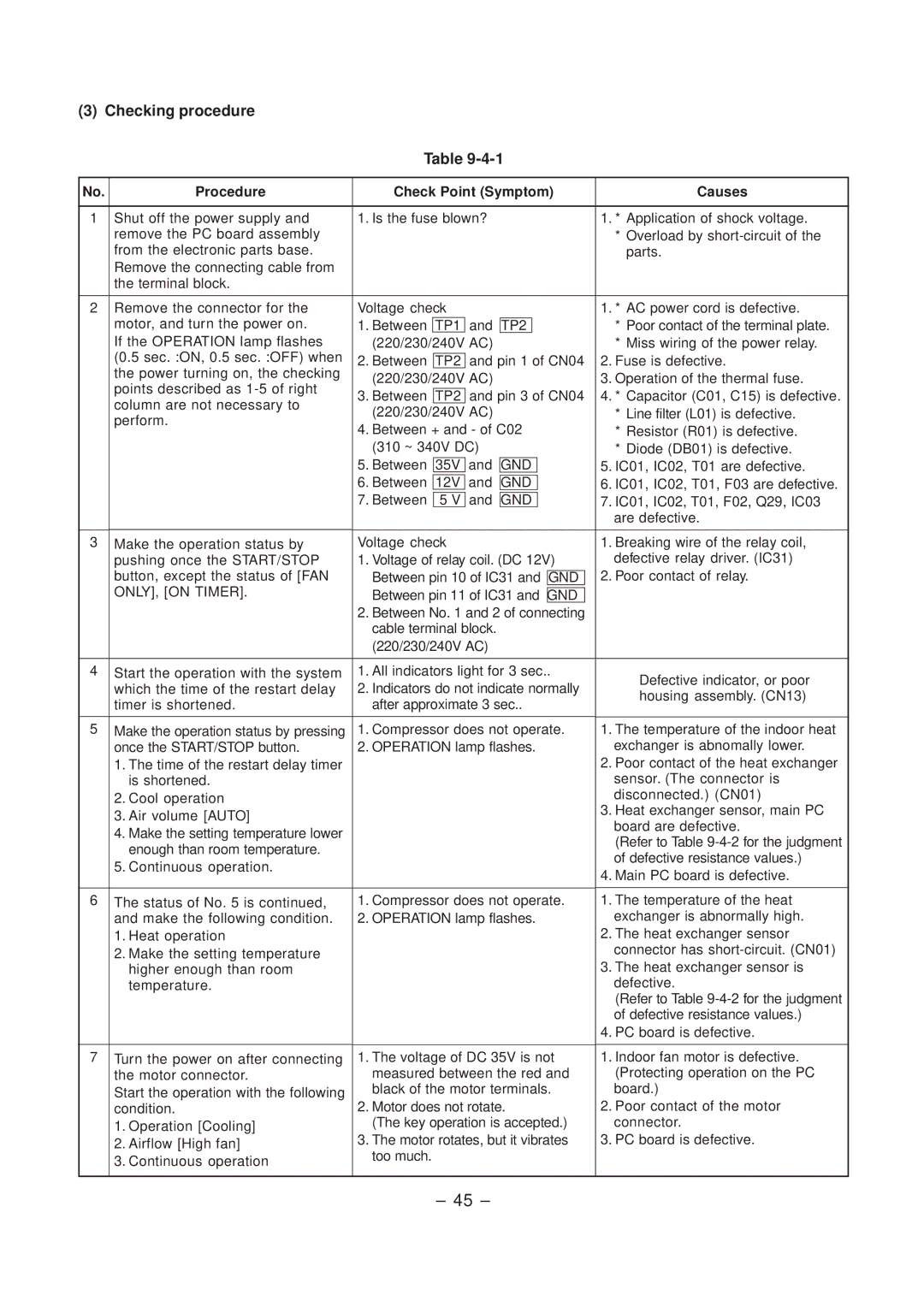
(3) Checking procedure
Table
No. | Procedure | Check Point (Symptom) |
| Causes | |||||||
|
|
|
|
|
|
|
|
|
|
| |
1 | Shut off the power supply and | 1. Is the fuse blown? |
|
|
|
|
| 1. * Application of shock voltage. | |||
| remove the PC board assembly |
|
|
|
|
|
|
|
| * Overload by | |
| from the electronic parts base. |
|
|
|
|
|
|
|
|
| parts. |
| Remove the connecting cable from |
|
|
|
|
|
|
|
|
|
|
| the terminal block. |
|
|
|
|
|
|
|
|
|
|
|
|
|
|
|
|
|
|
|
|
| |
2 | Remove the connector for the | Voltage check |
|
|
|
|
|
| 1. * AC power cord is defective. | ||
| motor, and turn the power on. | 1. Between |
| and |
|
|
|
|
| * Poor contact of the terminal plate. | |
| TP1 | TP2 |
|
|
|
| |||||
| If the OPERATION lamp flashes | (220/230/240V AC) |
|
|
|
|
| * Miss wiring of the power relay. | |||
| (0.5 sec. :ON, 0.5 sec. :OFF) when | 2. Between |
| and pin 1 of CN04 | 2. Fuse is defective. | ||||||
| TP2 | ||||||||||
| the power turning on, the checking | (220/230/240V AC) |
|
|
|
|
| 3. Operation of the thermal fuse. | |||
| points described as |
|
|
|
|
| |||||
|
|
|
|
|
|
|
|
|
|
| |
| 3. Between | TP2 | and pin 3 of CN04 | 4. * Capacitor (C01, C15) is defective. | |||||||
| column are not necessary to | ||||||||||
| (220/230/240V AC) |
|
|
|
|
| * Line filter (L01) is defective. | ||||
| perform. |
|
|
|
|
| |||||
| 4. Between + and - of C02 | * Resistor (R01) is defective. | |||||||||
|
| ||||||||||
|
| (310 ~ 340V DC) |
|
|
|
|
| * Diode (DB01) is defective. | |||
|
| 5. Between | 35V | and | GND |
|
|
| 5. IC01, IC02, T01 are defective. | ||
|
| 6. Between | 12V | and | GND |
|
|
| 6. IC01, IC02, T01, F03 are defective. | ||
|
| 7. Between | 5 V | and | GND |
|
|
| 7. IC01, IC02, T01, F02, Q29, IC03 | ||
|
|
|
|
|
|
|
|
|
| are defective. | |
|
|
|
|
|
|
|
|
|
|
| |
3 | Make the operation status by | Voltage check |
|
|
|
|
|
| 1. Breaking wire of the relay coil, | ||
| pushing once the START/STOP | 1. Voltage of relay coil. (DC 12V) | defective relay driver. (IC31) | ||||||||
| button, except the status of [FAN | Between pin 10 of IC31 and |
|
| 2. Poor contact of relay. | ||||||
| GND | ||||||||||
| ONLY], [ON TIMER]. | Between pin 11 of IC31 and |
|
|
|
| |||||
| GND |
|
| ||||||||
|
| 2. Between No. 1 and 2 of connecting |
|
| |||||||
|
| cable terminal block. |
|
|
|
|
|
|
| ||
|
| (220/230/240V AC) |
|
|
|
|
|
|
| ||
|
|
|
|
|
|
|
|
|
|
|
|
4 | Start the operation with the system | 1. All indicators light for 3 sec.. | ü | Defective indicator, or poor | |||||||
|
|
|
|
|
|
|
|
| |||
| which the time of the restart delay | 2. Indicators do not indicate normally | ý | housing assembly. (CN13) | |||||||
| timer is shortened. | after approximate 3 sec.. | þ |
| |||||||
5 | Make the operation status by pressing | 1. Compressor does not operate. | 1. The temperature of the indoor heat | ||||||||
| once the START/STOP button. | 2. OPERATION lamp flashes. | exchanger is abnomally lower. | ||||||||
| 1. The time of the restart delay timer |
|
|
|
|
|
|
|
| 2. Poor contact of the heat exchanger | |
| is shortened. |
|
|
|
|
|
|
|
| sensor. (The connector is | |
| 2. Cool operation |
|
|
|
|
|
|
|
| disconnected.) (CN01) | |
| 3. Air volume [AUTO] |
|
|
|
|
|
|
|
| 3. Heat exchanger sensor, main PC | |
|
|
|
|
|
|
|
|
| board are defective. | ||
| 4. Make the setting temperature lower |
|
|
|
|
|
|
|
| ||
|
|
|
|
|
|
|
|
| (Refer to Table | ||
| enough than room temperature. |
|
|
|
|
|
|
|
| ||
|
|
|
|
|
|
|
|
| of defective resistance values.) | ||
| 5. Continuous operation. |
|
|
|
|
|
|
|
| ||
|
|
|
|
|
|
|
|
| 4. Main PC board is defective. | ||
|
|
|
|
|
|
|
|
|
| ||
|
|
|
|
|
|
|
|
|
|
| |
6 | The status of No. 5 is continued, | 1. Compressor does not operate. | 1. The temperature of the heat | ||||||||
| and make the following condition. | 2. OPERATION lamp flashes. | exchanger is abnormally high. | ||||||||
| 1. Heat operation |
|
|
|
|
|
|
|
| 2. The heat exchanger sensor | |
| 2. Make the setting temperature |
|
|
|
|
|
|
|
| connector has | |
|
|
|
|
|
|
|
|
| 3. The heat exchanger sensor is | ||
| higher enough than room |
|
|
|
|
|
|
|
| ||
| temperature. |
|
|
|
|
|
|
|
| defective. | |
|
|
|
|
|
|
|
|
|
| (Refer to Table | |
|
|
|
|
|
|
|
|
|
| of defective resistance values.) | |
|
|
|
|
|
|
|
|
|
| 4. PC board is defective. | |
|
|
|
|
|
|
|
|
|
|
| |
7 | Turn the power on after connecting | 1. The voltage of DC 35V is not | 1. Indoor fan motor is defective. | ||||||||
| the motor connector. | measured between the red and | (Protecting operation on the PC | ||||||||
| Start the operation with the following | black of the motor terminals. | board.) | ||||||||
| condition. | 2. Motor does not rotate. | 2. Poor contact of the motor | ||||||||
| 1. Operation [Cooling] | (The key operation is accepted.) | connector. | ||||||||
| 2. Airflow [High fan] | 3. The motor rotates, but it vibrates | 3. PC board is defective. | ||||||||
| 3. Continuous operation | too much. |
|
|
|
|
|
|
|
|
|
|
|
|
|
|
|
|
|
|
|
| |
|
|
|
|
|
|
|
|
|
|
|
|
– 45 –