OUTDOOR UNIT
SERVICE MANUAL SPLIT TYPE
R410A
SPECIFICATIONS
CONTENTS
PRECAUTION FOR SAFETY
OUTDOOR UNIT REFRIGERATING CYCLE DIAGRAM
Original instruction
Generic Denomination: Air Conditioner
Explanation of indications
Definition of Protective Gear
DANGER
Explanation of illustrated marks
BURST HAZARD
Warning Indications on the Air Conditioner Unit
Confirmation of warning label on the main unit
– 5 –
Precaution for Safety
DENGER
– 6 –
– 7 –
– 8 –
– 9 –
Relocation
Disposal
Explanations given to user
Declaration of Conformity
2.Cautions on Installation/Service
New Refrigerant R410A
1. Safety Caution Concerned to New Refrigerant
3.Pipe Materials
4.Tools
General tools Conventional tools can be used
– 12 –
1-1-1. 4-WayAir Discharge Cassette Type
1. SPECIFICATIONS
1-1.Indoor Unit
– 13 –
– 14 –
<Twin type>
– 15 –
<Triple type>
1-1-2.Concealed Duct Type <Single type>
– 17 –
– 18 –
– 19 –
1-1-3.Under Ceiling Type <Single type>
Page
– 21 –
– 22 –
1-1-4.High Wall Type Twin type
– 23 –
– 24 –
– 25 –
– 26 –
1-1-6.Slim Duct Type <Twin type>
Page
– 28 –
1-1-7.High Static Duct Type <Single type>
1-2.Outdoor Unit
– 29 –
1-3.Operation Characteristic Curve
– 30 –
RAV-SP1604AT8Z ZG-E, -TR RAV-SP1104AT7Z ZG
– 31 –
RAV-SP1104AT8Z ZG-E, -TR RAV-SP1404AT8Z ZG-E, -TR
RAV-SP1404AT7Z ZG RAV-SP1604AT7Z ZG
2. CONSTRUCTION VIEWS EXTERNAL VIEWS
2-1.Outdoor Unit
– 33 –
RBC-TWP30E2, RBC-TWP50E2Simultaneous Twin
<Liquid side>
– 34 –
RBC-TRP100ESimultaneous Triple Gas side
Gas side socket
RAV-SP140type
– 35 –
RAV-SP110type
RAV-SP160type
4. WIRING DIAGRAM
4-1.Outdoor Unit
– 36 –
5. SPECIFICATIONS OF ELECTRICAL PARTS
5-1.Outdoor Unit
– 37 –
6. REFRIGERANT R410A
6-1.Safety During Installation/Servicing
6-2.Refrigerant Piping Installation
6-2-1.Piping Materials and Joints Used
6-2-2.Processing of Piping Materials
1.Flare Processing Procedures and Precautions
1.Joints
Table 6-2-1Thicknesses of annealed copper pipes
Flare and flare nut dimensions for R22
Fig. 6-2-1Flare processing dimensions
Flare and flare nut dimensions for R410A
– 40 –
Nominal
2.Flare Connecting Procedures and Precautions
– 41 –
Outer diameter
6-4.Recharging of Refrigerant
Fig. 6-4-1Configuration of refrigerant charging
6-3.Tools
6-3-1.Required Tools
6-5-1.Materials for Brazing
6-5-2.Flux 1.Reason why flux is necessary
6-5.Brazing of Pipes
1.Silver brazing filler
6-5-3.Brazing
2.Characteristics required for flux
3.Types of flux
Never use gas other than Nitrogen gas
Instruction of Works
6-6.Instructions for Re-usePiping of R22 or R407C
– 45 –
If the definite conditions can be cleared
6-6-5.Final Installation Checks
– 46 –
Procedure
Cautions for using existing pipe
6-6-7.Recovery Method of Refrigerant
DANGER
7-1.Outdoor Unit Control
7-1-2.Print Circuit Board, MCC-1597Fan Motor IPDU
7-1-3.Print Circuit Board, MCC-1599Interface CDB
– 50 –
CN10 Red
– 51 –
CN05 Red
CN16 Red
REQUIREMENT
7-2.Outline of Main Controls
1.PMV Pulse Motor Valve control
2.Discharge temperature release control
3-2Heating fan control
3. Outdoor fan control
3-1Cooling fan control
– 53 –
5.Short intermittent operation preventive control
4.Coil heating control
REQUIREMENT
6.Current release control
9.High-pressurerelease control
7.Current release value shift control
8.Over-currentprotective control
– 55 –
10.Defrost control
– 56 –
1.Before troubleshooting
8. TROUBLESHOOTING
8-1.Summary of Troubleshooting
2. Troubleshooting procedure
– 58 –
1.Before troubleshooting
2.Troubleshooting procedure
Trouble
8-2.Troubleshooting
8-2-1.Outline of judgment
– 59 –
– 60 –
8-2-2.Others Other than Check Code
– 61 –
1 2 3
nCalling of sensor temperature display
– 62 –
Page
– 64 –
Error mode detected by indoor unit
– 65 –
Error mode detected by outdoor unit
– 66 –
– 67 –
Page
Display selection
Dip switch setup
LED display on outdoor P.C. board
– 69 –
Page
– 71 –
– 72 –
– 73 –
¡l l l
– 75 –
– 76 –
– 77 –
Check
Check and troubleshooting
– 78 –
Outdoor
– 79 –
Temperature sensor
– 80 –
Parts name
Checking procedure
– 81 –
Resistance value
<Contents>
9. SETUP AT LOCAL SITE AND OTHERS
9-1.Calling of Error History
<Procedure>
nIndoor unit power-ONsequence
– 83 –
9-3.Outdoor Unit
– 84 –
– 85 –
D805 D804 D803 D802 D801 D800
1.Outline
Enlarged view of LEDs
9-3-3.Others
1.Selection of LED display SW800, SW803 operation
– 86 –
lllll¡
lllll¡
– 89 –
<Specific operation>
SW804
– 90 –
SW804
10. ADDRESS SETUP
10-1.Address Setup Procedure
– 91 –
10-2.Address Setup & Group Control
10-2-1.System Configuration
– 93 –
Example
– 94 –
Change is necessary
Single system
10-3.Remote Controller Wiring
Wiring diagram
Simultaneous twin system
2, 5,
3, 6, 9 4, 7,
1 2 3 4 5 6 7 8 9 10 11 END
1 2 END
1 2 3 END
10-5.Confirmation of Indoor Unit No. Position
<Maintenance/Check list>
– 98 –
1.Setting the jumper wires and DIP switches
Model switching J800 to J803
12-2.Exchange of Compressor
12. HOW TO EXCHANGE COMPRESSOR
12-1.Exchanging Procedure of Compressor Outline
– 100 –
– 101 –
Contents
13. INSTALLATION MANUAL
ADOPTION OF NEW REFRIGERANT
Warning Indications on the Air Conditioner Unit
electric power supplies
– 102 –
Definition of Protective Gear
Installation
1 PRECAUTIONS FOR SAFETY
Selection of installation location
Electrical wiring
Relocation
104
Explanations given to user
EN-6
Accessory Parts
2 ACCESSORY PARTS AND REFRIGERANT
3 INSTALLATION OF NEW REFRIGERANT AIR CONDITIONER
Required Tools/Equipment and Precautions for Use
– 106 –
4 INSTALLATION CONDITIONS
Before installation
Refrigerant Piping
– 107 –
Installation Location
Necessary Space for Installation Unit mm
EN-12
5 REFRIGERANT PIPING
Installation of Outdoor Unit
– 108 –
For Reference
– 109 –
Optional Installation Parts Locally procured
Tightening of Connecting Part
Refrigerant Piping Connection
Refrigerant Pipe Length
6 AIR PURGING
110 –
Airtight test
111
How to open the valve
Wiring between Indoor Unit and Outdoor Unit
7 ELECTRICAL WORK
EN-22
– 112 –
Single system, Twin system, Triple system
23-EN
8 EARTHING
11 ANNUAL MAINTENANCE
Recovering Refrigerant
13 FUNCTIONS TO BE IMPLEMENTED LOCALLY
EN-26
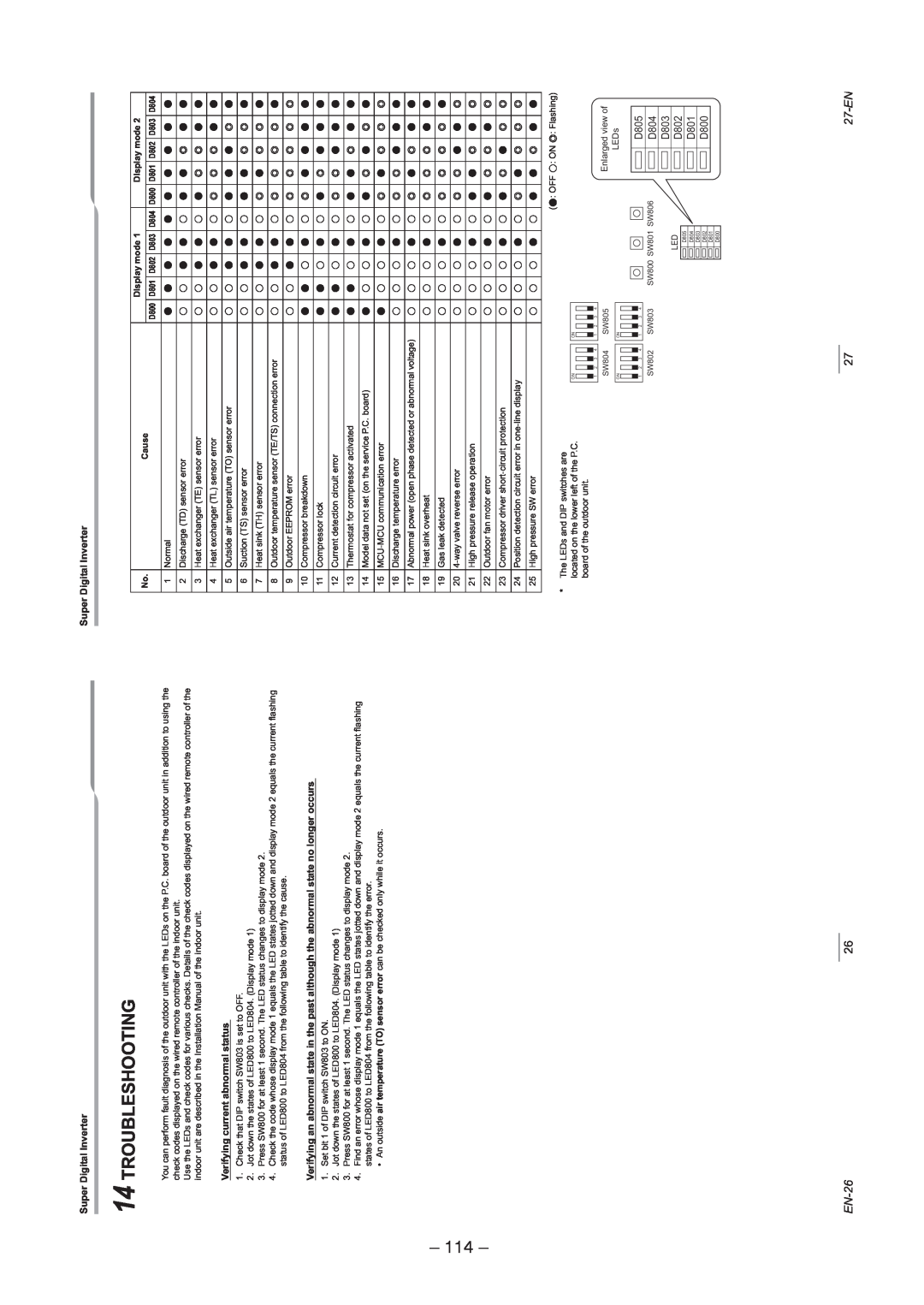
14 TROUBLESHOOTING
– 114 –
27-EN
EN-28
15 APPENDIX
115
29-EN
– 116 –
EN-30
31-EN
– 117 –
Declaration of Conformity
EN-32
118
14. DETACHMENTS
14-1.Outdoor Unit
1. Detachment
119
1. Detachment
2.Attachment
– 120 –
2.Attachment
1. Detachment
Procedure
– 121 –
2. Attachment
– 122 –
Detachment
Attachment
– 123 –
Detachment
Attachment
– 124 –
1. Detachment
2.Attachment
– 125 –
8Compressor 1. Detachment
2. Attachment
REQUIREMENT
– 126 –
– 127 –
10Compressor 1. Removal of defective compressor
3. Vacuuming
– 128 –
2. Mounting of compressor
4. Refrigerant charge
– 129 –
REQUIREMENT
REQUIREMENT
1. Detachment
15. EXPLODED VIEWS AND PARTS LIST
Outdoor Unit
– 131 –
Inverter Assembly
133
Outdoor Unit
– 134 –
– 135 –
Inverter Unit
136
– 137 –
Outdoor Unit
– 139 –
Inverter Unit
– 140 –
– 141 –
WARNINGS ON REFRIGERANT LEAKAGE
Check of Concentration Limit
TOSHIBA CARRIER CORPORATION