Split Type
Contents
Original instruction
Explanation of indications
Explanation of illustrated marks
Work undertaken Protective gear worn
Indication Explanation
Confirmation of warning label on the main unit
Description
Precaution for Safety
Denger
Proceeding with the repair work
Refrigerant used by this air conditioner is the R410A
Resistance and water drainage
Explanations given to user
Relocation
Declaration of Conformity
Model names with a rating of 12 kW and below outdoor units
Safety Caution Concerned to New Refrigerant
Pipe Materials
Copper pipe Piping
Flare nut
Tools
General tools Conventional tools can be used
Specifications
Indoor Unit
Way Air Discharge Cassette Type
Single type
Twin type
Triple type
1604AT8-TR
Concealed Duct Type Single type
1104AT8-TR 1404AT8-TR
562BT-E 802BT-E Model Indoor unit
562BT-E Indoor unit
Under Ceiling Type Single type
562CT-E 802CT-E Model Indoor unit
562CT-E Indoor unit
High Wall Type Twin type
562KRT-E Indoor unit
Compact 4-Way Cassette 600 × 600 Type Twin type
1104AT8-TR
562MUT-E Indoor unit
Slim Duct Type Twin type
564SDT-E Indoor unit
High Static Duct Type Single type
Outdoor Unit
RAV-SP
Operation Characteristic Curve
Operation characteristic curve, 50Hz Super Digital Inverter
Operation characteristic curve, 60Hz Super Digital Inverter
RAV-SP1104AT7 Z ZG RAV-SP1404AT7 Z ZG RAV-SP1604AT7 Z ZG
Capacity variation ratio according to temperature
Cooling Heating
Construction Views External Views
Name
RBC-TWP30E2, RBC-TWP50E2 Simultaneous Twin
Model RBC
RBC-TRP100E Simultaneous Triple Gas side
Liquid side
Gas side socket
Liquid side socket
RAV-SP140 type
RAV-SP110 type
RAV-SP160 type
Wiring Diagram
Specifications of Electrical Parts
Parts name Type Specifications
Safety During Installation/Servicing
Refrigerant Piping Installation
Refrigerant R410A
Piping Materials and Joints Used
Joints
Flare Processing Procedures and Precautions
Processing of Piping Materials
Flare and flare nut dimensions for R410A
3 Dimensions related to flare processing for R410A / R22
Flare and flare nut dimensions for R22
Nm kgfm
Flare Connecting Procedures and Precautions
Wrenches available on the market
Recharging of Refrigerant
Required Tools
Low temperature brazing filler
Flux Reason why flux is necessary
Brazing of Pipes
Materials for Brazing Silver brazing filler
Characteristics required for flux
Types of flux
Piping materials for brazing and used brazing filler/flux
Brazing
Instructions for Re-use Piping of R22 or R407C
Basic Conditions Needed to Reuse the Existing Pipe
Restricted Items to Use the Existing Pipes
Branching Pipe for Simultaneous Operation System
Final Installation Checks
Existing pipe SW Switch
Recovery Method of Refrigerant
Procedure
Handling of Existing Pipe
Reference outside diameter Wall thickness
Outdoor Unit Control
Circuit Configuration and Control Specifications
Print Circuit Board, MCC-1596 Compressor Ipdu
Print Circuit Board, MCC-1597 Fan Motor Ipdu
CN700 Blue CN500 Red
CN504 Blue
F500
Print Circuit Board, MCC-1599 Interface CDB
F03
CN05 Red CN10 Red CN16 Red
CN23 Red
Discharge temperature release control
Outline of Main Controls PMV Pulse Motor Valve control
Cooling fan control
Outdoor fan control
Heating fan control
Short intermittent operation preventive control
Coil heating control
Current release control
Temperature range SP110
Current release value shift control
Over-current protective control
High-pressure release control
High-pressure switch/Compressor case thermostat control
Defrost control
Start of heating operation
Normal To Abnormal To
Troubleshooting
Summary of Troubleshooting
Before troubleshooting
Troubleshooting procedure
Wireless remote controller type
Trouble Confirmation of lamp display
Outline of judgment
Troubleshooting
Lamp indication Check code Cause of trouble occurrence
Ready
Others Other than Check Code
Lamp indication Check code
Contents
Check Code List Outdoor
Reset
Timer Ready Flash F01
Error mode detected by indoor unit
Cause of operation Status
Error mode detected by outdoor unit
Series
Operation of diagnostic function
Power supply error of remote controller, Indoor
LED display on outdoor P.C. board Dip switch setup
Diagnostic Procedure for Each Check Code Outdoor Unit
Display selection
F07 Display Display 2 Heat exchanger temp. sensor TL error
Display Display 2 Heat exchanger temp. sensor TE error
F06
F12 Display Display 2 Suction temp. sensor TS error
F13 Display Display 2 Heat sink temp. sensor TH error
H01 Display Compressor break down
H02 Display Compressor lock
L10 Display
YES
Display Display 2 Communication error between MCU
Display 1 Display 2 Unset model type → Refer to L10 column
Display High pressure SW system error
P04
Normally operate?
P19 Display Way valve inverse error
P07 Display Heat sink overheat error
P15 Display Gas leak detection
Heating operation
Position detection circuit error
Single operation check for outdoor fan
P26
Display 2 Short-circuit of compressor drive element
Temperature sensor
TA, TC, TCJ, TE, TS, to sensors Representative value
TD,TL sensors Representative value
TA, TC, TCJ, TE, TS, to sensors
Parts name Checking procedure
Table Inspection of outdoor unit main parts
Resistance value
Position
Setup AT Local Site and Others
Calling of Error History
Contents
Group Control Operation
Indoor unit power-ON sequence
By feed unit Automatic address judgment
Initial communication
Usual regular Communication
Defrost control
Function Set position Control contents
Max. frequency of compressor
Operation part
Specifications Operation contents
Display part
Others Selection of LED display SW800, SW803 operation
Switch Function / Contents Refer
Display selection list
Error display
¥¥ll¡
Setup
Opening
Pulse
Display
SW804 Operation when pushdown button switch SW801 is pushed
Specific operation for maintenance check SW801, SW804
Specific operation
For check RY703, CN703 check
Address Setup
Address Setup Procedure
System Configuration
Address Setup & Group Control
Terminology
Only turning on source power supply Automatic completion
Automatic Address Example from Unset Address No miswiring
Example
Standard One outdoor unit Single Twin Triple SP160 only
Remote Controller Wiring
Wiring diagram
Single system Simultaneous twin system
Simultaneous triple system SP160 only
Address Setup Manual setting from remote controller
Procedure
Confirmation of Indoor Unit No. Position
To know the position of indoor unit body by address
Button
Maintenance/Check list
Replacement of the Service P.C. Board 4316V417 MCC-1599
Setting the jumper wires and DIP switches
Model switching J800 to J803
Part name Function Setting
HOW to Exchange Compressor
Exchanging Procedure of Compressor Outline
Exchange of Compressor
100
Contents
Definition of Protective Gear
102
Work undertaken Protective gear worn
103
To Disconnect the Appliance from the Main Power Supply
104
Explanations given to user
Relocation
Accessory Parts
Required Tools/Equipment and Precautions for Use
Tools/equipment Use How to use tools/equipment
105
106
Before installation
Airtight test
Necessary Space for Installation Unit mm
Installation Location
107
Installation of Outdoor Unit
Knockout procedure
108
For Reference
Optional Installation Parts Locally procured
Tightening of Connecting Part
109
Refrigerant Piping Connection
Refrigerant Pipe Length
110
Air Purge
How to open the valve
Wiring between Indoor Unit and Outdoor Unit
111
Replenishing refrigerant
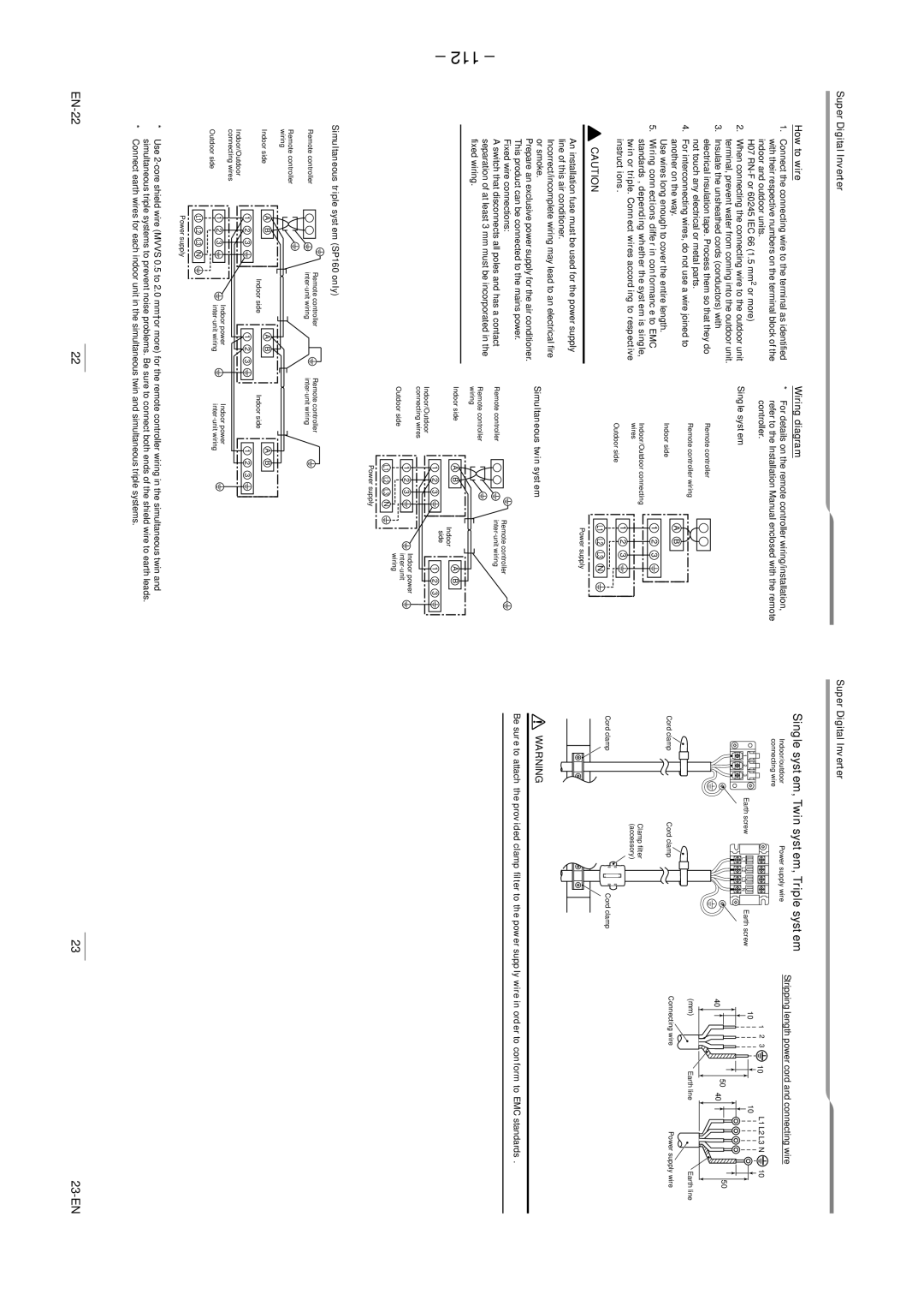
Super Digital Inverter How to wire Wiring diagram
112
Single system, Twin system, Triple system
Single system
113
Recovering Refrigerant
Handling Existing Pipe
114
Super Digital Inverter Cause Display mode
Verifying current abnormal status
115
116
7DB
117
Declaration of Conformity
Detachments
118
RAV-SP1104AT8 7, RAV-SP1404AT8 7, RAV-SP1604AT8 7 series
Detachment
119
120
Part name Procedure Remarks
121
Part name Procedure
122
123
124
125
Compressor 1. Detachment
Requirement
126
127
No. Part name Procedure Remarks
Compressor 1. Removal of defective compressor
128
Mounting of compressor
Vacuuming
Refrigerant charge
129
Exploded Views and Parts List
130
131
1104AT7ZG
721
Inverter Assembly
132
133
134
135
1404AT7ZG
Inverter Unit
136
137
138
139
1604AT7ZG
140
141
Check of Concentration Limit
Toshiba Carrier Corporation