4.8 Error! Style not defined. | 4 Replacement Procedures |
M2.5x4 black flat head screw
MIC cable
CCD cable
LCD FL cable
Cable fillister
Wireless Lan antenna
TAPE
CN10
CN7
![]()
![]() CN12
CN12
Cable fillister
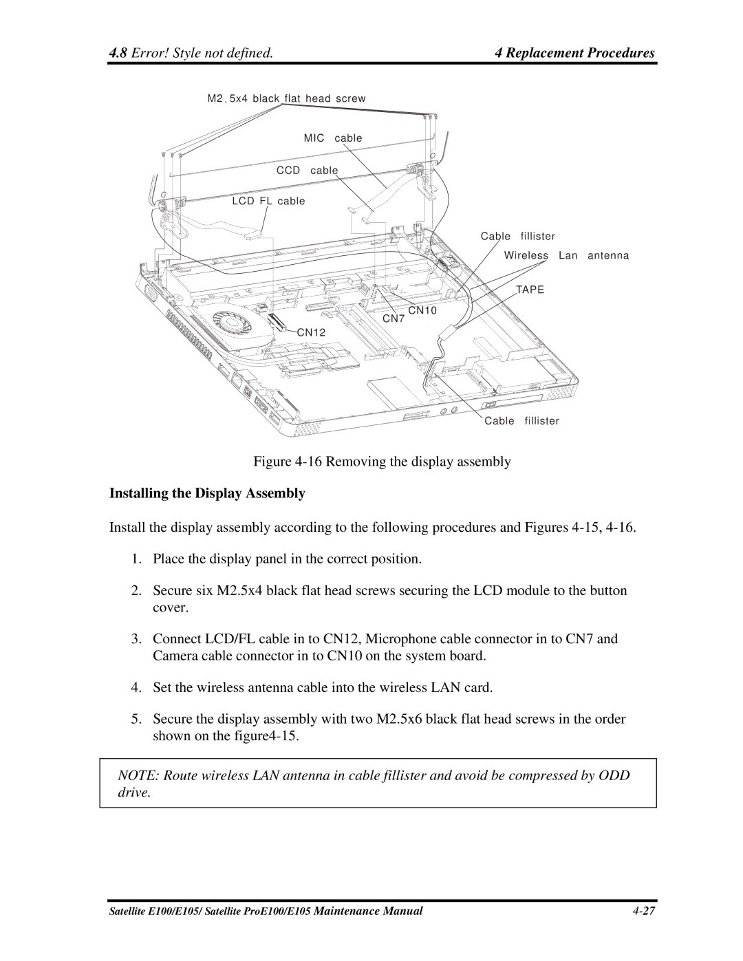
Figure 4-16 Removing the display assembly
Installing the Display Assembly
Install the display assembly according to the following procedures and Figures
1.Place the display panel in the correct position.
2.Secure six M2.5x4 black flat head screws securing the LCD module to the button cover.
3.Connect LCD/FL cable in to CN12, Microphone cable connector in to CN7 and Camera cable connector in to CN10 on the system board.
4.Set the wireless antenna cable into the wireless LAN card.
5.Secure the display assembly with two M2.5x6 black flat head screws in the order shown on the
NOTE: Route wireless LAN antenna in cable fillister and avoid be compressed by ODD drive.
Satellite E100/E105/ Satellite ProE100/E105 Maintenance Manual |