4 Replacement Procedures | 4.19 Power board, Switch board, Touch Pad board |
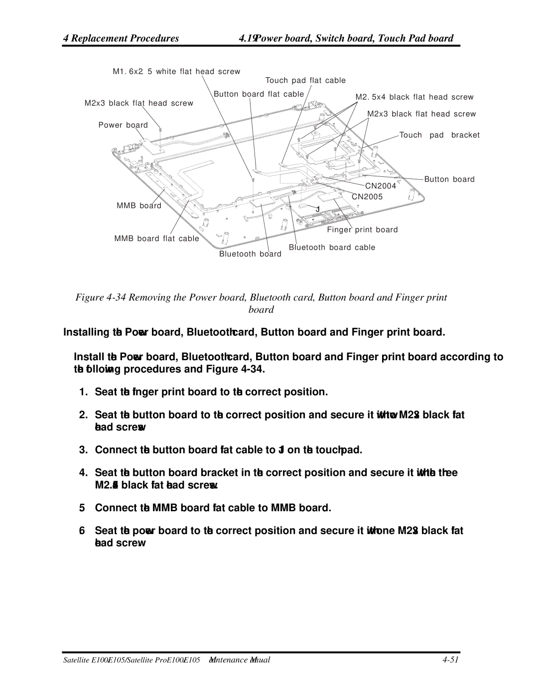
M1. 6x2. 5 white flat head screw
Touch pad flat cable
Button board flat cable
M2x3 black flat head screw
Power board
M2. 5x4 black flat head screw M2x3 black flat head screw
Touch pad bracket
| Button board |
| CN2004 |
| CN2005 |
MMB board | J1 |
| |
| Finger print board |
MMB board flat cable |
|
| Bluetooth board cable |
| Bluetooth board |
Figure 4-34 Removing the Power board, Bluetooth card, Button board and Finger print
board
Installing the Power board, Bluetooth card, Button board and Finger print board.
Install the Power board, Bluetooth card, Button board and Finger print board according to the following procedures and Figure
1.Seat the finger print board to the correct position.
2.Seat the button board to the correct position and secure it with two M2x3 black flat head screws
3.Connect the button board flat cable to J1 on the touch pad.
4.Seat the button board bracket in the correct position and secure it with the three M2.5x4 black flat head screws.
5.Connect the MMB board flat cable to MMB board.
6.Seat the power board to the correct position and secure it with one M2x3 black flat head screw.
Satellite E100/E105/ Satellite ProE100/E105 Maintenance Manual |