4 Replacement Procedures | Error! Style not defined. Display Assembly |
4.8 Display Assembly
Removing the Display Assembly
CAUTION: Use care to avoid that the antenna cable is not caught between the display assembly and computer.
Remove the display assembly according to the following procedures and Figures
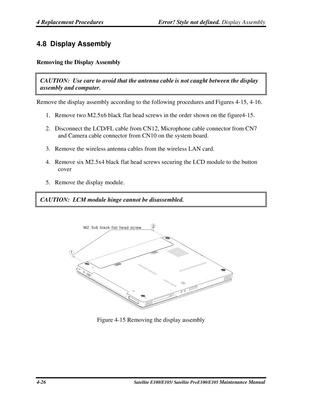
1.Remove two M2.5x6 black flat head screws in the order shown on the
2.Disconnect the LCD/FL cable from CN12, Microphone cable connector from CN7 and Camera cable connector from CN10 on the system board.
3.Remove the wireless antenna cables from the wireless LAN card.
4.Remove six M2.5x4 black flat head screws securing the LCD module to the button cover
5.Remove the display module.
CAUTION: LCM module hinge cannot be disassembled.
M2 | . 5x6 black flat head screw | 2 |
|
1
Figure 4-15 Removing the display assembly
Satellite E100/E105/ Satellite ProE100/E105 Maintenance Manual |