Error! Style not defined. Error! Style not defined. | 4 Replacement Procedures |
4.5Top Cover
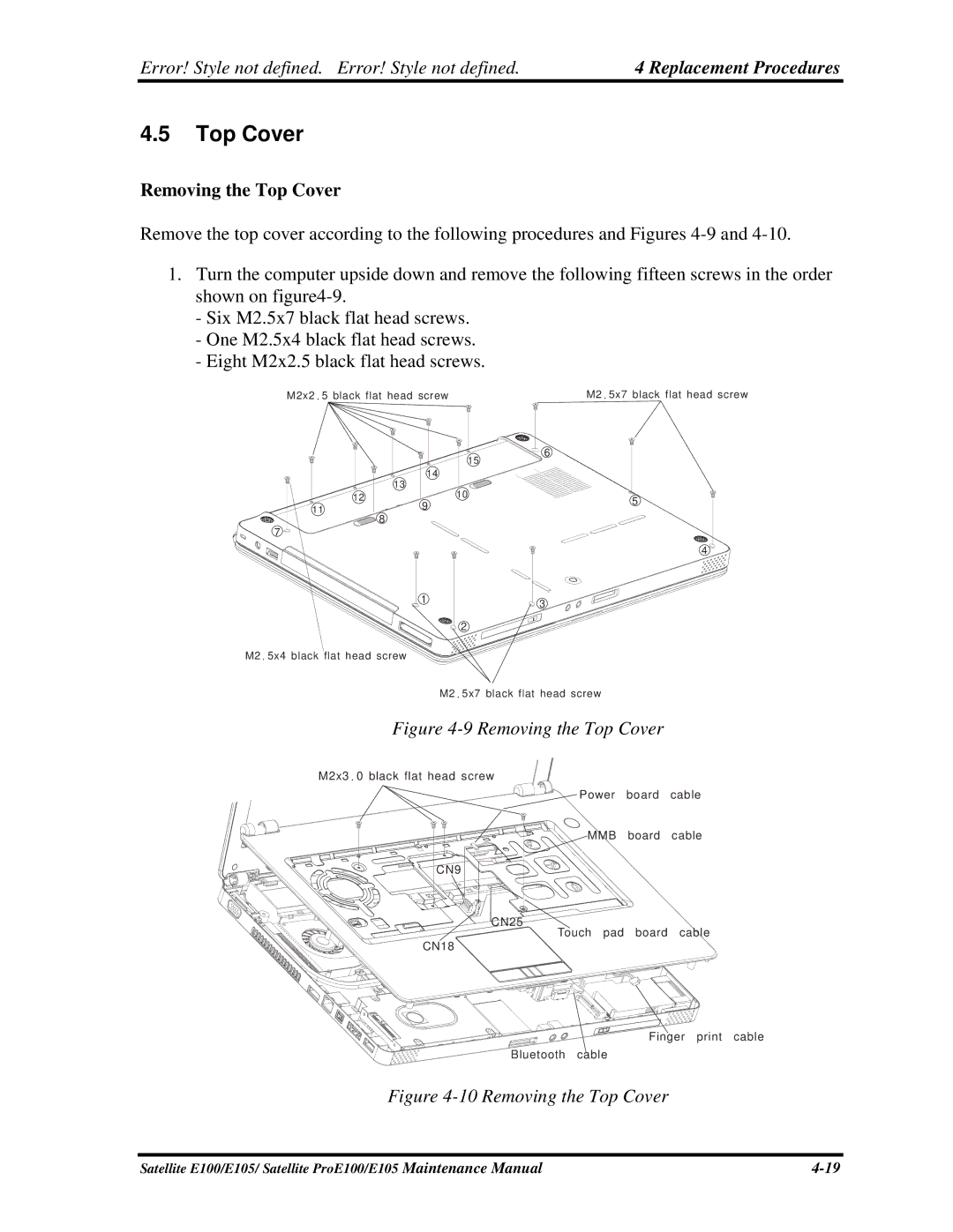
Removing the Top Cover
Remove the top cover according to the following procedures and Figures
1.Turn the computer upside down and remove the following fifteen screws in the order shown on
-Six M2.5x7 black flat head screws.
-One M2.5x4 black flat head screws.
-Eight M2x2.5 black flat head screws.
M2x2. 5 black flat head screw | M2. 5x7 black flat head screw |
13
12
11
![]()
![]()
![]()
![]()
![]()
![]()
![]()
![]()
![]()
![]() 8 7
8 7 ![]()
![]()
M2. 5x4 black flat head screw
| 6 |
| 15 |
14 |
|
| 10 |
9 | 5 |
|
4 ![]()
1 | 3 |
|
![]()
![]()
![]() 2
2
M2. 5x7 black flat head screw
Figure 4-9 Removing the Top Cover
M2x3.0 black flat head screw
CN9
CN25
CN18
Power board cable
MMB board cable
Touch pad board cable
Finger print cable
Bluetooth cable
Figure 4-10 Removing the Top Cover
Satellite E100/E105/ Satellite ProE100/E105 Maintenance Manual |