6 F 3 H 1 0 0 1
7. Panels
7.1 Graphic Display Panel
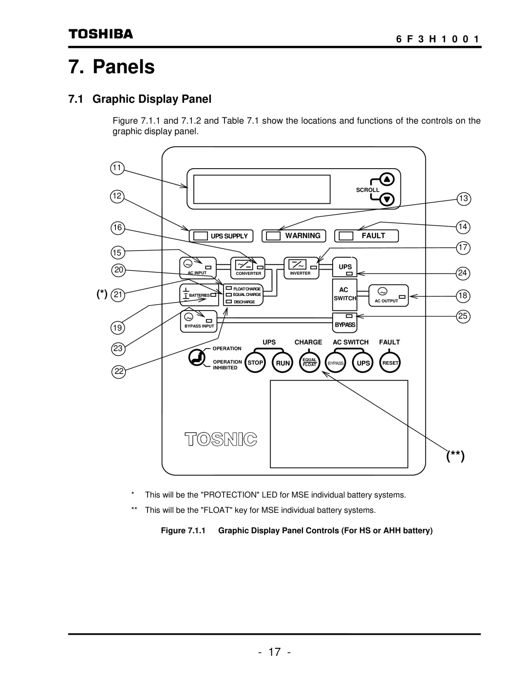
Figure 7.1.1 and 7.1.2 and Table 7.1 show the locations and functions of the controls on the graphic display panel.
11
12
16
UPS SUPPLY
WARNING
SCROLL
13
14
FAULT
15 ![]()
20 | ~ | ~ |
AC INPUT | CONVERTER | |
(*) 21 |
| FLOATCHARGE |
BATTERIES | EQUALCHARGE | |
|
| DISCHARGE |
| ~ |
|
~
INVERTER
UPS
AC
SWITCH
17
24
~ | 18 | |
AC OUTPUT | ||
|
25
19 | BYPASS INPUT |
| |
23 | UPS |
OPERATION |
BYPASS
CHARGE AC SWITCH FAULT
| OPERATION STOP | RUN | EQUAL | BYPASS | UPS RESET |
| FLOAT | ||||
22 | INHIBITED |
|
|
|
|
|
|
|
|
|
(**)
*This will be the "PROTECTION" LED for MSE individual battery systems.
**This will be the "FLOAT" key for MSE individual battery systems.
Figure 7.1.1 Graphic Display Panel Controls (For HS or AHH battery)
- 17 -
