6 F 3 H 1 0 0 1
6. Controls and Circuit Configuration
If the unit begins to emit smoke or strange odors, immediately WARNIN turn off circuit breakers 52R and 72B.
G Continued use may result in fire. Contact the Toshiba Service
Center .
6.1 Panel Controls
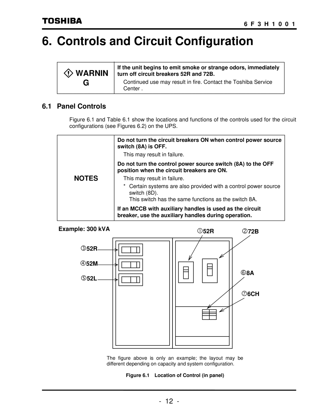
Figure 6.1 and Table 6.1 show the locations and functions of the controls used for the circuit configurations (see Figures 6.2) on the UPS.
Do not turn the circuit breakers ON when control power source switch (8A) is OFF.
This may result in failure.
Do not turn the control power source switch (8A) to the OFF position when the circuit breakers are ON.
NOTES | This may result in failure. |
*Certain systems are also provided with a control power source switch (8D).
This switch has the same functions as the switch 8A.
If an MCCB with auxiliary handles is used as the circuit breaker, use the auxiliary handles during operation.
Example: 300 kVA | c52R | d72B |
| ||
e52R |
|
|
f52M |
|
|
g52L |
| h8A |
|
| |
|
| i6CH |
The figure above is only an example; the layout may be different depending on capacity and system configuration.
Figure 6.1 Location of Control (in panel)
- 12 -
